Nishita
Introduction to Basics and a mini Robot
The first day was a relief since the language we used was English and not Electronics (I had no background in electronics). I put together the simplest of circuits; learned to work a motor. Everything was simple enough to understand and watching my first robot make its way across the table was the highlight of that day. We also learned to solder; never have I been so proud of my burns.
Shopping for Electronics
SP road was electronics and hardware Disneyland. It was an alternate geek universe. In all directions I observed hawkers not with balloons but wires, batteries and motors. Crowded with electronics enthusiasts, SP road heard a lot of lingo being thrown around, words heavy with a superior knowledge of electronics that I didn't dare ask about. We purchased the components off the list at Vishal electronics; its functioning busy but meticulous. It took a while.
Lemon Battery
It was fascinating to observe the multimeter flicker as I connected the two terminals of the lemon battery to it. I essentially pierced the lemon with a copper wire and zinc nail to make the battery. I later learned that any citrus fruit can be utilised to produce electric charge.
Creating a toy
The toy I made was something I named a 'Sassbot'. Using a simple circuit consisting of a switch, battery and motor, the sassbot rotated till switched off. I placed the circuit on a thick board so it would rotate smoothly and gave it cotton padding below to reduce the noise. It was then covered with a body of paper with the word "Nope" written on its face. Its function was to allow its user to answer a difficult proposal in the negative while keeping it funny to avoid awkward 'no's . It's one of those toys that aren't really useful for anything but idle entertanment. More people than not said they would buy a similar product for its comic value.
Making a Switch
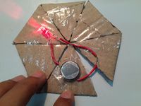
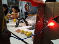
For this assignment we split up into groups to come up with an unconventional idea for a switch. We put together a Jigsaw puzzle that lit up an LED upon completion. Alternately I also implemented Vikram's idea of a swinging switch where a pendulum (in this case: a crocodile clip) swung to and fro the circuit, lighting up the LED for short intervals.
Use of resistors, diodes and capacitors
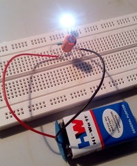
I didn't get the idea of a Capacitor at first but once I did I could not believe how simple it was. Though I did not go into the details of the inner workings of the three components, I got the hang of their utility. Also, learning the color coding for the resistors was a bit of a task but by the end of class I was making successful circuits. The same goes for the working of a Breadboard.
Resistor=The higher its power, the more controlled the charge in a circuit. Capacitor=Stores charge from a battery to be used by the circuit, this could increase the amount of charge in a circuit and can also use that charge free of a battery for a short period of time. Diode=Gives the flow of current a direction. A unidirectional flow is healthier for a circuit as it prevents burning up of its components due to a surge.
Potentiometers
Above is a video of an LED growing brighter as the resistance in the circuit is decreased with the help of a potentiometer. Learning to use a potentiometer was more than I'd hoped for. In the past I had pretentiously taken apart speakers in order to figure out how the volume worked. On this day I learned that the basics were simple enough to be picked up by a child if provided with the right guidance. Above is a video of an LED growing brighter as the resistance in the circuit is decreased with the help of a potentiometer.
Learning to work Speakers
The above is a video of a speaker making a distinct clicking sound. When resistance is reduced via a potentiometer, the clicking sound gets louder. During this project I also learned the use of LDRs. Since they are light sensitive, if the LDR in this circuit was exposed to light, the speed of its clicks would increase noticeably and vice versa.
Creating an amplifier
While making the Amplifier we were introduced to ICs and Audiojacks. This is also when the circuit diagrams got a little complicated. The difference here is that we could play sounds of our choice using the audiojack. We first practiced several times in class and were asked to make a working amplifier at home without using Breadboards. At first I tried several times to make an amplifier using a circuit containing wires as the medium but to no avail, since there were a few cross connections. The video above shows the workings of my amplifier for which I used a PCB instead.


