Vikrant Mishra
Contents
- 1 Introduction
- 2 Introduction to the Basics
- 3 Class Activities // Tasks Performed
- 3.1 Making and LED light blink
- 3.2 The Touch Me Not Monster
- 3.3 Pulse Detecting Sensor
- 3.4 Turbidity Sensor
- 3.5 Observations// Conclusions
- 3.6 Drawings of the Future
- 3.7 Body Add-on from the Future// 'Talk that talk'
- 3.8 Maps and Frequencies
- 3.9 Data Visualization/ LDR Frequency Graph
- 3.10 LED VU Meter using Potentiometer
- 3.11 EMF Sensor// Developing our own Sensor
- 4 Final Project
Introduction
Hey! I’m Vikrant. I’m an Industrial arts and design practitioner at Srishti Institute of Art, Design and Technology. I find passion in working with different sorts of materials and creating things. I believe that every good design can be a piece of art. Design technologies, art and illustrations are some of my passions and I'd love mastering all of these someday. Through last three years I've tried mastering materials like wood, metal and sun-board. The products and designs that I've worked on, majorly revolve around human lifestyle and daily engagement. Apart from designing I also cook, paint and do poetry.
Introduction to the Basics
Arduino and other components
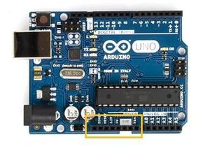
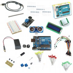
The first day mostly involved figuring out the things we were not familiar with. This involved figuring out how commands work on Arduino and how the setup works. We started with learning all the functions and properties of different electrical components. Later we moved on to Arduino Uno and learned how to connect components to it. After we got done figuring out the basics, we learned how to program stuff. We started with the most basic one, which was to make a LED light blink. We entered the numerical components required for command to function and it worked. We later experimented with other components like piezo alarm, IR sensor etc. We learned how bread-board is used and how it’s an easy way to experiment things rather than soldering the whole circuit to a certain PCB board.
Class Activities // Tasks Performed
Making and LED light blink
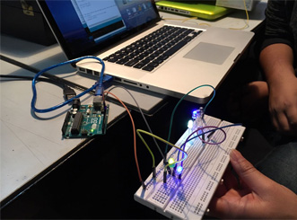
Firstly you will need to plug one end of a wire into the '5v' Power output on the arduino, and the other end into the positive section of the breadboard. Then you need to plug one end of a wire into the ground ('GND') Power output, and the other end into the Negative section of the Breadboard. Finally, you need to plug one end of the resistor from the Negative section of the Breadboard, to any horizontal line on the main section. Later we connected LEDs on the bread-board. We wanted to connect multiple LEDs and so we connected more in the series. Attach a wire from digital port '0' on your Arduino to the hole directly above the resistor and run the program.
The Touch Me Not Monster
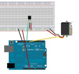
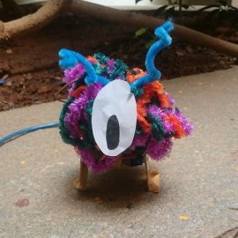
The team I was working under made this toy. The toy consisted of various components like Server motors, Arduino UNO, IR sensor and batteries. We have an IR receiver connected to +5v, ground, and pin 11. We also have a servo with three wires. The red wire is +5v. The black or dark brown wire is ground and the remaining wire usually yellow is the signal wire which we have connected to pin 9 although it could be any digital output pin. We played with the output a little bit so that the servo behaves erratically. To make this toy work we needed to add an external 5 volt supply that we did using a power converting pin. To make it look innocent and cute, we covered it with colorful threads to make it look appealing. When any motion was detected near the IR sensor, the toy would start shaking and jumping.
Pulse Detecting Sensor
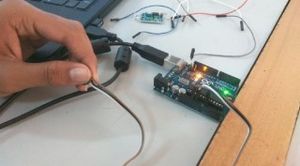
The activity involved mainly to use the pulse sensor and show the readings on the serial monitor.
Turbidity Sensor
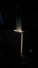
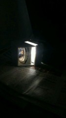
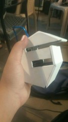
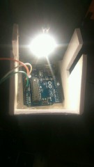
The task involved building and caliberating our own turbidity sensor. After understanding the connections it seemed easy as it was based on a LDR and the serial readings recorded by the software. After the connections we tested it and it worked fine. Later we placed it in the box it started misbehaving. It took us a little time to adjust things in the sensor and the case to avoid the mistake in readings. We tested it with samples and it worked fine. A slightest change of pin made a huge difference to the working. It was interesting to learn making of such sensors as the huge machines are built on the base of such a small connections. The exercise gave us the understanding of handling of fragile sensors and multiple samples.
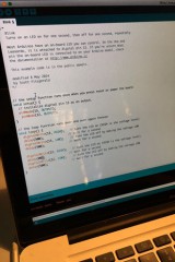
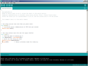
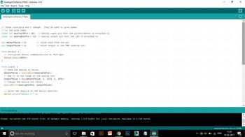
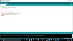
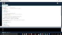
The program that we used is here:
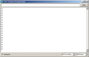
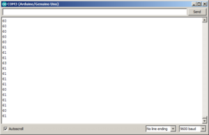
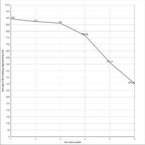
The graph we obtained from the readings from various samples is displayed below on the graph:
Observations// Conclusions
> Reading for the sample with just water shows the highest of the reading, because of the uniform/ proper passing of light rays without any dispersion.
> As the concentration of milk in water increased the frequency detected by LDR started decreasing.
> Reading of the sample with just milk varied from sensor to sensor of different groups. Though it was expected that it will show the least of the received frequencies, it showed more than it should have. Most probably this happened because of the internal dispersion of light in the test-tube and the color of the milk. (i.e white) White reflects the light.
Drawings of the Future
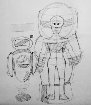
The first drawing shows the robot 'Eva' from the movie 'Wall-E'. I considered this as future because in the movie, 'Eva' carried/ saved a plant inside her. This plant later ended up saving the world, thousands of years after. The second drawing shows a human after 100-200 years. It shows how human body has completely got rid of useless body extensions like ear lobes, eye lashes, body hair etc.
Body Add-on from the Future// 'Talk that talk'
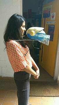
For this exercise I designed a body extension called 'Talk that talk'. This extension from future is supposed to read what you want to express/ say from your brain, using neurotransmitters. The machine in front of your head gives necessary commands and dialogues according to your expressions/ gestures/ thoughts. The display in front is for visual aids to the blind or visually impaired person. The task was performed by me and Rhea Banthia.
Maps and Frequencies
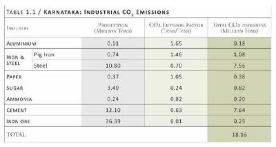
1) Carbon dioxide emissions and sources in Karnataka. 2) Pm10 densities across Bangalore.
Data Visualization/ LDR Frequency Graph
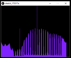
The following graphs/ data visualization was obtained using LDR in the circuit. This was something new and advanced to learn as it involved processing. The graphs obtained, the code and the serial monitor readings are following.
LED VU Meter using Potentiometer
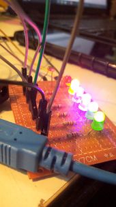
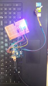
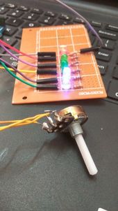
This project shows you how to take inputs from a sensor (potentiometer here) and get LEDs to respond and visually display the peaks and troughs of the readings.
EMF Sensor// Developing our own Sensor
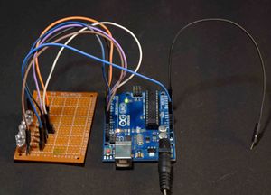
An EMF meter can measure electromagnetic fields, which are usually emitted from man-made sources such as electrical wiring, or magnetometers fields, which occur naturally in Earth's geomagnetic field and are emitted from other sources where direct current is present. We had to make a detector for EMF using the Arduino uno. After researching on the internet we realized that the EMF detector requires only a wire that is connected to the input pin of the Arduino. Using the EMF readings we connected LED's to blink according to the EMF readings. To work with detection easily, we also made a small solenoid using copper wire and a 9V battery to induce EMF around the end of wire, which acted as an antenna.
Final Project
HerboPet
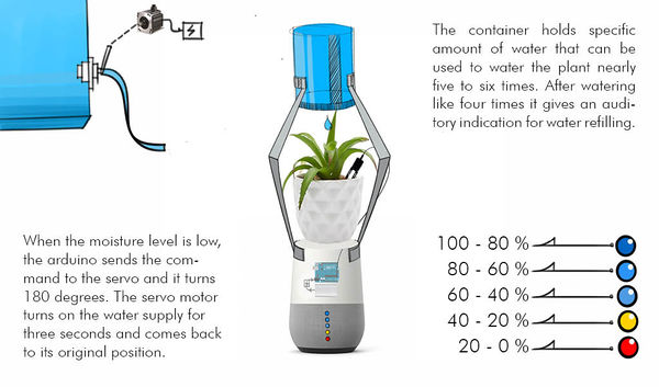
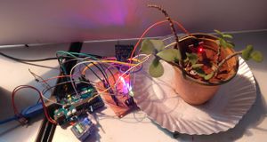
'HerboPet' is an extension for house plants and succulents designed in a way that it waters itself when it feels like drinking. Taking moisture level into account, it will water itself when there is less moisture in soil. In a way, the pot is the communication link between human and plants as we don't how much water is required by them and when. We, humans, water the plants as and when we remember or fix a particular time which might not be convenient time for the plants. Also, saving water and growing healthier veggies and flowers with a self-watering planter becomes much easier.
Working
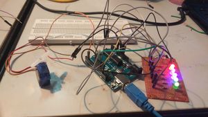
The planter waters itself when there is low moisture content in soil. There is an indication of the amount of moisture on the LED meter.
Components
Moisture sensor
Text to Speech module
Servo motor
Arduino Uno
LEDs
Resistors
Speakers
Wires
Circuit
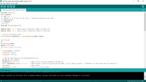
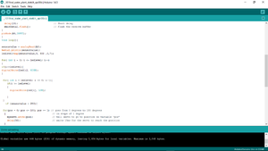
Code
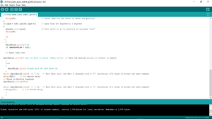
The following is the coding for the Self watering planter in 3 parts.
Part 1, Part2, Part3
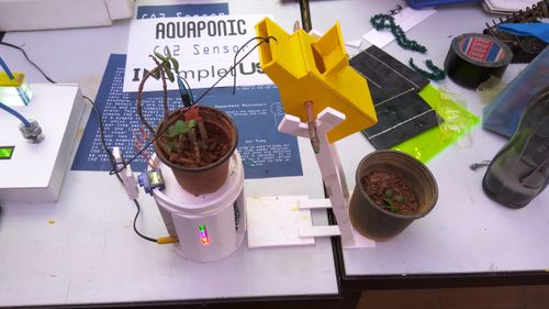
Prototype
The final prototype involved working with the structure and various materials. The following picture is of the final model. The yellow container on the right holds water and drops it in the pot when pulled by the servo motor attached to it. The container is elevated and put on a pulley at certain height so that it sits exactly where its supposed to. The base of the pot with the plant has the LED meter that shows the level of moisture in soil.
