Bhawna
Contents
Micro Robots
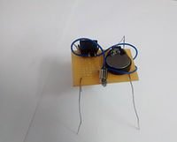
I eagerly entered the class that I had waited for quite some time, looking forward to some hands-on work and to further explore my interest in electronics. The idea of making a robot in the first class was exciting although it was the most basic circuit, this was the first time I was doing this stuff practically. Understanding the connections along with the soldering experience was an assertion of my interest.
Trip to S.P.Road
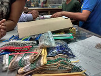
From figuring out the extensive list of materials to the bus routes to S.P. Road and finding the exact shop was a bit of a task. The market was loaded with all kinds of hardware, tools and electronics shops. The time and effort it took to buy all the components was unbelievable. We spent about 5 hours at the shop counting, negotiating, bargaining to make do with. The shopkeeper, although had to put up with all our tantrums, offered us some refreshing drinks as a gesture that I think was welcomed by most of us in the heat. It was a good feeling to be able to recognize the components at the shop, considering the long list.
Project-Lemon Battery
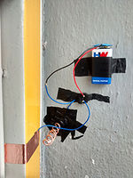
This was an easy one since this is something that is taught in textbooks in schools, so it was easy to recall. I used zinc galvanized nail (SS nail found in a hardware shop near dairy cross) as the anode or the negative terminal and a copper wire (found in an electrical shop near dairy cross) as the cathode or the positive terminal. Stuck the two in the lemon making sure that they do not touch. Although the battery did work according to the voltage reading on the multimeter (fluctuating reading) but it was not enough voltage to light an led.
Making the first Sensor
My group brainstormed on various ideas of what an action and reaction of a switch could be and we finally came up with an idea similar to that of a door alarm, where it basically buzzed when the door was open. So the action of opening the door was switch on, whereas closed door would mean that the switch is off. This exercise brought a lot of different meaning to the switch in terms of what it could be in a circuit further allowing a lot of different applications for a switch.
Components- Resistance
Since I could recall the concept of resistors from my class 12th physics it was relatively easier for me to follow the class and create circuits successfully.
Components:potentiometer, capacitor, diode
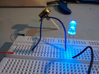
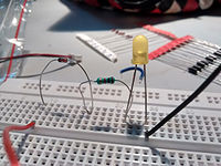
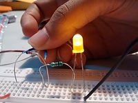
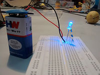
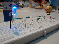
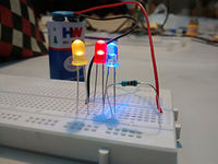
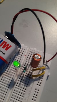
Since I'm familiar with the concepts of a potential divider, capacitor, and diode since school time, following the circuits was easier and made a lot of sense as I recalled my lessons. Although I have never really used these components on circuits like this, so figuring out how the connections work and what side goes where was a first. Still applying these concepts in a circuit of my own would be a hard task, for example, the capacitor in theory stores charge but once we connected it the charge stored was capable of lighting the led for merely a second, such applications would require a further study of these components.
More Components: Transistors
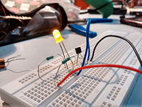
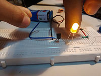
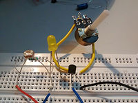
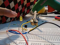
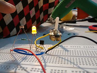
During my class 12th, the chapter on semiconductors and transistors was one of my favorites but I never got to see its actual functioning and how the amplifying or controlling aspect of the transistor would work. This was the class that I enjoyed the most although it was a bit more work to follow the circuit since it was a bit more complicated from what we had been doing. And it required a lot of patience to figure out the knee point resistance that was required to replace the potentiometer from the initial circuit and eventually control the led brightness using an LDR. And the effect of light and everybody else's shadows in the room did not make it easy to fix on one value as the LDR's resistance kept variating accordingly.
555 IC
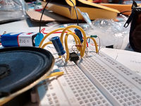
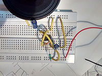
The IC was mostly a new concept for me since we barely covered it in school but since it's a major component and invention to have lead into a computer age I was more involved in understanding the circuit and its working. Making the circuit for the 555IC oscillator was not as difficult as understanding the functioning of the IC and each pin. I variated the inputs by changing the capacitors and the resistors from the input pin to obtain different outputs which were in the form of sound since we used a speaker to generate the output. There were reactions from the class as these weird high pitched noises were generated especially when without warning. I did try using a dc motor in place of the speaker but did not get any satisfying result. There seemed to be no change in the motor's rotation speed at all.
Project- Toy or a Kinetic Structure
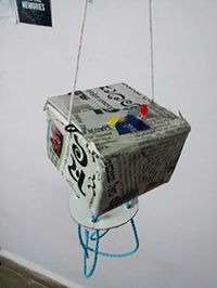
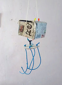
The idea of making a project on my own and experimenting with circuits based on what I learnt the past 2 weeks was quite exciting. But the result was not the same. I really felt challenged at thinking of an idea, but then my pre-class excitement kicked in and I tried playing around with some circuits that I always wanted try but never had the opportunity. Played with blinking, flashing and alternate flashing LEDs using the 555 IC. And I succeeded at most of the circuit but incorporating it in a toy or a kinetic structure was a task. So I aimed at making an alien-like structure with a rotating bottom which has tentacles attached and alternate flashing LEDs for eyes. But the disappointing part was once I soldered the connections the speed of the flashing of LEDs slowed down even though I used the same capacitor, so I. changed the capacitor to a higher capacitance one. And by the time the toy reached class I faced more problems in the soldered circuit and it didn't work like I wanted to.
Video of the working prototype circuit
Amplifier Using LM386 IC
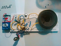
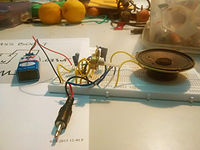
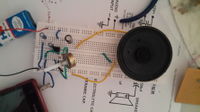
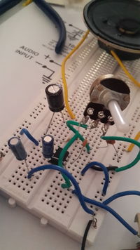
Making an amplifier was quite easy than expected. Now electronics seemed like something that I understood and I was building a lot more interest. Initially I faced some issue with soldering the audio jack, guessing I need work on my soldering skills. But the prototype circuit worked out fine,
Project- Making an Amplifier
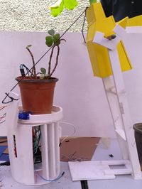
After failing at soldering while doing the toy project I was not looking forward at this one as much. So I tried to follow Mr. Bala's advice and carefully planned the whole circuit along with the structure that I wanted to use for the amplifier and planned and placed the switch, potentiometer knob for volume, wire, and audio jack. The planning helped a lot. In my first attempt, the circuit worked just fine. And that helped with my confidence. Although I did not innovate on the structure from the acoustics aspect but I plan to add a hollow cylinder on top with a cloth padding to make the amplified sound softer and clearer. The good thing is I can actually use it.
Arduino
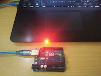
Blink LED
Although this code was easy to follow and pretty basic, it was still a bit exciting for me since i have never tried coding and this was my first experience and the idea of being able to control things now was fun. And there was a scope for a lot of learning since Arduino and the whole concept of a micro controller was new for me.
CODE:
// the setup function runs once when you press reset or power the board void setup() {
pinMode(13, OUTPUT);
}
// the loop function runs over and over again forever void loop() {
 digitalWrite(13, HIGH);
 delay(1000);
 digitalWrite(13, LOW);
 delay(1000);
}
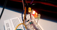
Knight Rider
This code was a bit of a task, since it was lengthy for us. I did not know of how to do it in a short-cut method. Basically the lights would switch on-off in order from led 1 to 10th and back the same way. The following is the short-cut method code.
Video for the knight rider lights
CODE:
void setup() {
 // put your setup code here, to run once:
 pinMode(13, OUTPUT);
 pinMode(12, OUTPUT);
  pinMode(11, OUTPUT);
 pinMode(10, OUTPUT);
 pinMode(9, OUTPUT);
 pinMode(8, OUTPUT);
 pinMode(7, OUTPUT);
  pinMode(6, OUTPUT);
 pinMode(5, OUTPUT);
 pinMode(4, OUTPUT);
}
void loop() {
 // put your main code here, to run repeatedly:
 int i;
  for(i=4;i<13; i++){
   Serial.println(i);
   digitalWrite(i, HIGH);
   delay(100);
   digitalWrite(i, LOW);
   delay(100);
  }
   for(i=13;i>=5; i--){
   Serial.println(i);
   digitalWrite(i, HIGH);
   delay(100);
   digitalWrite(i, LOW);
   delay(100);
  }
 }
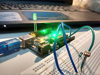
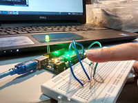
Using an LDR to control LED brightness through Arduino
By controlling the amount of light that reaches the LDR, which one could do with the hand. Hence this made it like a hand proximity sensing light control system. The code was done such that the LED would light up when the hand is close to it the LED would light up and vice-versa. This attempt made coding a bit more clearer to me and introduced more functions as well as using the Serial monitor.
CODE:
void setup() {
 // put your setup code here, to run once:

 pinMode ( 13, OUTPUT);
 Serial.begin(9600);
 int value;
}
void loop() {
// put your main code here, to run repeatedly:
int value=analogRead(A0); Serial.println(value);
 if ( value<= 250){
   digitalWrite(13,HIGH);
 }
 else {
   digitalWrite(13,LOW);
 }
Running a Servo motor through Arduino
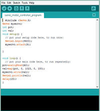
Since i did not own a servo motor i could not try this code initially, but I did work with the servo motor for my project. It was quite easy.Instead of controlling on and off command as in case of LED(HIGH-LOW) we control the position of the servo motor in terms of angles.
CODE:
- include <Servo.h>
Servo myservo;
int pos = 0;
void setup() {
myservo.attach(9);
}
void loop() {
 for(pos = 0; pos <= 180; pos += 1)
 {
   myservo.write(pos);
   delay(15);
 }
 for(pos = 180; pos>=0; pos-=1)
 {
   myservo.write(pos);
   delay(15);
 }
}
Magical object
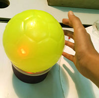
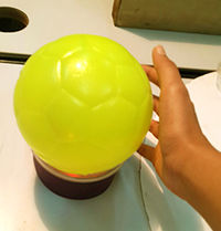
This magical object was a difficult ideating process. Me and Prarthana worked together to make something that we call "The Magic Ball". Inspired from those future telling crystal balls. Our initial idea was to have a 'NO' and 'YES' show up through LEDs but since that did not work out we tried to control different LEDs using different LDRs, so basically through some dramatical hand movements and some build up we change colors of the magic ball through our hand directions. We faced errors in the code. So we changed our idea to control the brightness of the light similar to the class assignment but using moe LEDs for brighter light. So as one moves their hand away the light becomes brighter and ultimatley changes to yellow from the initial red.
CODE:
void setup() {
 // put your setup code here, to run once:
 pinMode (12,OUTPUT);
 pinMode (10,OUTPUT);
pinMode (8,OUTPUT); pinMode (6,OUTPUT); int i; Serial.begin(9600);
}
void loop() {
 // put your main code here, to run repeatedly:
 int i= analogRead (A0);
Serial.println (i); if (i<500) {digitalWrite (12,HIGH);} else {digitalWrite (12, LOW);} if (i<150) {digitalWrite (12, LOW);}
if (i<400) {digitalWrite (10,HIGH);} else {digitalWrite (10,LOW);} if (i<150) {digitalWrite (10, LOW);}
if (i<300) {digitalWrite (8, HIGH);} else {digitalWrite (8,LOW);} if (i<150) {digitalWrite (8, LOW);}
if (i<150) {digitalWrite (6,HIGH);} else {digitalWrite (6,LOW);}
}
The MS logo Turtle-bot
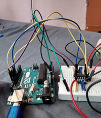
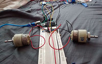
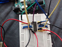
As the name suggests the project was based of off the turtle in MS Logo. The Robot represented by a turtle would be commanded as in MS Logo and similarly the turtle would move and draw. The group struggled a lot initially since the method that we followed was mostly trial and error to figure out which circuit would fit our project idea. There were a huge load of ideas and Robot circuits available online, but the issue was that not all of them were easy, comrehendable, or even correct. The basic idea of how the robot would work was clear. We wanted to use two motors to control the movement through two wheels and a servo motor to control the pen. I had some knowlegde of the dc motor controller IC chip- L293D, since I had researched on it for some personal project but never really tried. So we went ahead and used L293D to control the motors (specifically dc geared motors 100rpm).
Initial prototype level CODE for the movement of the Robot:
void setup() {
 // put your setup code here, to run once:
 pinMode(13,OUTPUT);// Right motor forward
 pinMode(10,OUTPUT);// Left motor forward
 pinMode(9,OUTPUT);// Right motor reverse
 pinMode(12,OUTPUT);// Left motor reverse
 myservo.attach(8);
}
void loop() {
// put your main code here, to run repeatedly:
}
void moveForward()
{
 Serial.println("moveForward");
 digitalWrite(13,HIGH);
 digitalWrite(10,HIGH);
 delay(10000);
 digitalWrite(9,LOW);
 digitalWrite(12,LOW);
 delay(10000);}
void moveBackward()
 {
   Serial.println("moveForward");
   digitalWrite(13,LOW);
 digitalWrite(10,LOW);
 delay(10000);
 digitalWrite(9,HIGH);
 digitalWrite(12,HIGH);
 delay(10000);}
 void turnRight()
 {
   Serial.println("turnRight");
   digitalWrite(13,LOW);
 digitalWrite(10,HIGH);
 delay(10000);
 digitalWrite(9,LOW);
 digitalWrite(12,LOW);
 delay(10000);}
 void turnLeft()
 {
    Serial.println("turnLeft");
   digitalWrite(13,HIGH);
 digitalWrite(10,LOW);
 delay(10000);
 digitalWrite(9,LOW);
 digitalWrite(12,LOW);
 delay(10000);}
 void allstop()
{
 Serial.println("turnLeft");
   digitalWrite(13,LOW);
   digitalWrite(10,LOW);
   delay(10000);
   digitalWrite(9,LOW);
   digitalWrite(12,LOW);
   delay(10000);
 }
Another problem that we faced was with the voltage being used to power the motors. Since the motors were 12v, the 9v battery would run out in a day and we would get stuck figuring out what went wrong. Ultimately we used an 11v li ion battery, which solved the problem. But that was not the end of it. More complications came up as we proceeded with project, while soldering the final circuit to make a shield for the arduino, the mechanics of the Turtle came up, figuring out the wifi module working.
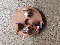
This what the final robot looks like:
