Saurabh
From (art)scienceblr
My name is Saurabh Bedarkar, studying in 2nd year at Srishti Institute of Art, Design and Technology. Currently I am in Sensors, Detectors and Probes course. I have taken this course so that I could Experiment around with the interaction between humans or say nature with technology.
Contents
Micro Robot
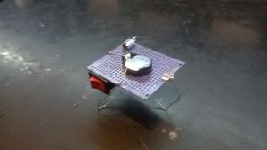
This was my first robot and was really exciting to build one. It was fascinating that how we can convert a vibrating motion into kinetic motion with just a motor, switch and a battery. And also I learned soldering circuits. Click here to check the video.
Trip to SP Road
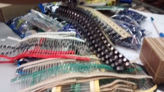
Trip to SP road was really a explorative trip for me were I got to know many new things or components which are available around us. The street had all the required electrical components through which one can make his own computer or a mobile. I was fascinated by seeing all the big motors, heavy machinery, and also the types of different electrical components which exists. Specially I got to know many types of sensors available in the market like the ultrasonic sensor, motion sensor, color sensor, etc.
Introduction to Components
Battery
Making your own Battery
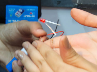
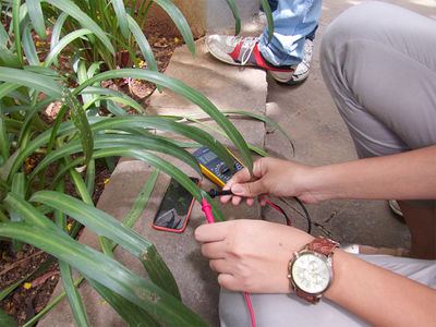
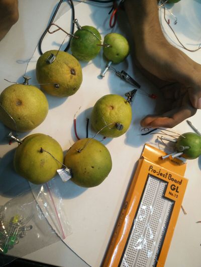
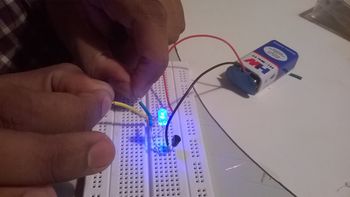
We had to make our own switch. While thinking about the switch we all thought of our body as a switch as it conducts electricity. We started with a 9v battery but the LED didn't lit up. So we staked 9 batteries in series making a 81v battery which worked really well. It was a breath taking experiment as we were passing 81v through our body. We also tried the same experiment with plants and leaves.We also had to make our own battery using lemons, household lemons. It was interesting to see how we can use a simple lemon as a battery.
Resistors
Fixed Resistors
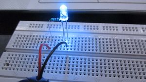
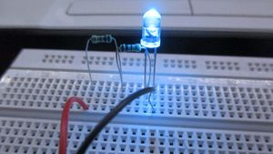
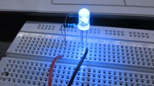
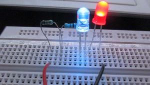
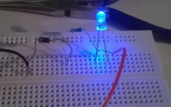
In this experiment I experimented with limiting current through resistor. We controlled the LED brightness by placing the resistors in series combination and parallel combination.
Variable Resistors
Potentiometer
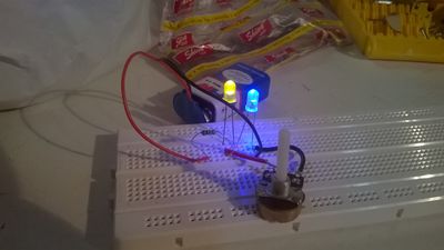
Potentiometer is really helpful device as it control the amount of current flowing. At first we had to put resistors in series to control the flow but then this is really helpful. It was fun working with potentiometer as we controlled the LED brightness. Click here to see the video.
Thermistor
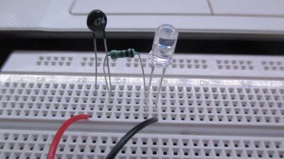
Thermistor is a temperature sensitive resistor which changes resistance with change in temperature. We made a simple circuit which lights up the LED when the temperature is high.Click here for the video.
LDR
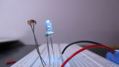
Light Depending Resistor is resistor which changes its resistance with light. It was fun playing with the light and shadow to control the brightness of the LED.Click here for the video.
Capacitors, Diodes, Transistors
These are important components for a complex circuit. This allowed me to simplify the switch which we had made by using transistor to amplify the power flowing without using many batteries.
555 oscillator
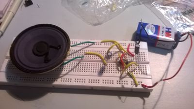
555 is a Integrated Circuit which is a timer IC. We used it to create sound pulse through a speaker. It also changed the sound as the resistance changed.Click here to check out the video.
Make a Toy
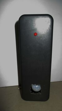
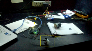
I took inspiration from an game character i.e an android robot from Portal. The major components I used are Motion sensor, 555IC, and a red LED. At first I tried many circuits but most of them failed but finally the circuit worked. I used a Arduino which powers the motion sensor, and when the motion is detected the 555IC circuit powers on with a red flashing LED making the sound of gunshots. It was a difficult job to make this circuit as we had to solder the circuit on a PCB.Click here to get fired.
Amplifier
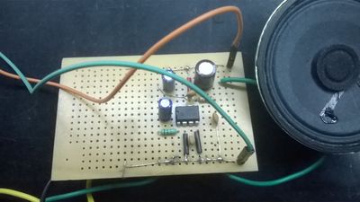
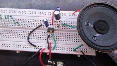
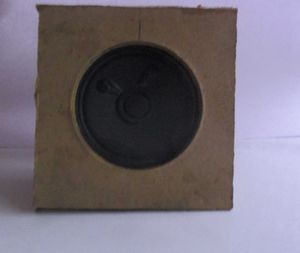
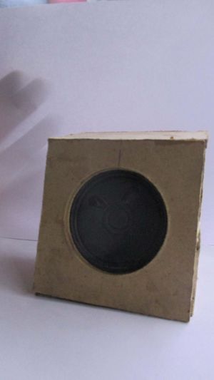
This was the first time that I made a speaker. It was interesting to make the amplifier. Also to cover the speaker I made a MDF box as it is considered a good material for speaker box. In the circuit we used a LM386 Amplifier IC. And also we have done a bass boost circuit. It was a tedious task as the circuit was not working after soldering. But after many tries, failure and frustration finally the circuit worked. Click here to check out the video.
Arduino
Blink
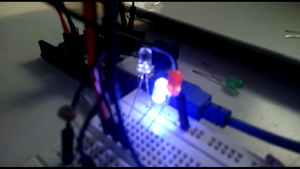
This was the first time we were going to learn Arduino though I knew a little bit of it, I was excited to learn it. The first task was make a LED blink. After making the circuit I realized that Arduino was like a remote control, we just need to tell it what we want it to do in its coding language and with perfect connects we could make awesome thingsKnight Rider
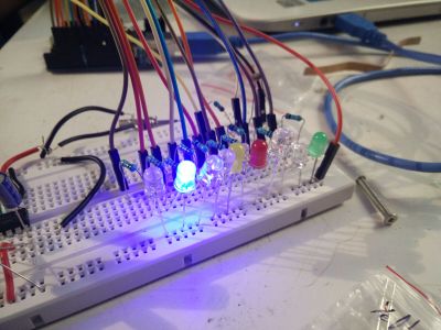
After the first task of LED blinking we had to achieve a effect of LED glowing in series as shown in a movie Knight Rider. It was fun working with it and trying mess around with it using different sensors to control the effect.
Magical Object
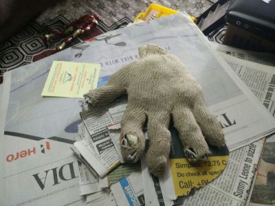
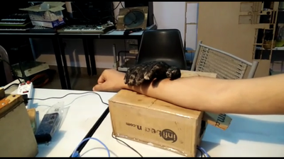
The task was to create a magical object using Arduino power. I teamed up with Sumit as it was a group activity. We made a magic hand which grabs you when you go near it.Click here to get your hand grabbed.
