Difference between revisions of "Shivon"
(→Introductory Class) |
(→555 Oscillator) |
||
| Line 65: | Line 65: | ||
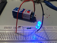
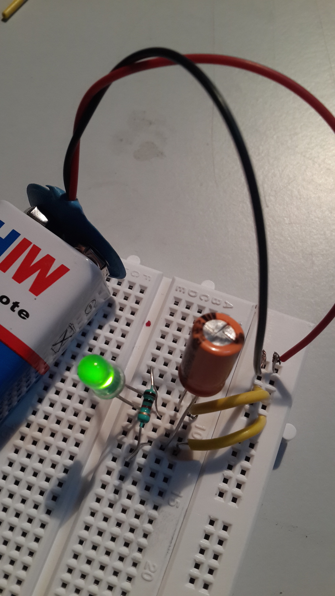
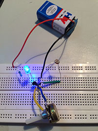
IC was something very different to work with. Every leg had a different connection. Building the circuit on the breadboard was a little difficult for me since I didn’t understand the connection at first. We attached a speaker and it started making amusing sounds. We tried changing the values of the capacitors and resistors and the sounds kept changing accordingly. Attaching an LDR made it even more interesting as it made funny sounds. | IC was something very different to work with. Every leg had a different connection. Building the circuit on the breadboard was a little difficult for me since I didn’t understand the connection at first. We attached a speaker and it started making amusing sounds. We tried changing the values of the capacitors and resistors and the sounds kept changing accordingly. Attaching an LDR made it even more interesting as it made funny sounds. | ||
| − | [[File:ic2.jpg]] | + | [[File:ic2.jpg]] [[File:ic.jpg]] [[File:th.png|250px|]] |
=='''[[PROJECTS]]'''== | =='''[[PROJECTS]]'''== | ||
Revision as of 15:40, 17 October 2015
MicroRobots
Day 1:
Introductory Class
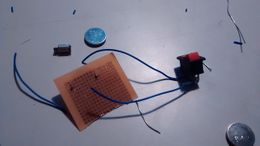
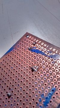
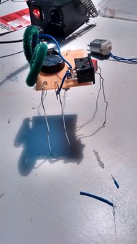
To start with, I took this course because I didn’t have any knowledge about electronics at all. And sensors are something that could be inculcated in a lot of products and would also help me further in designing products. So on the first day we built a tiny robot of our own with a motor, battery and battery holder, switch and wires to complete the circuit. This was the first time I actually made a circuit on the PCB board and soldered it. First when I tried to solder, I found it a bit easy but later I realized that it has a particular technique. The soldering iron should be placed on the board first at a certain angle then the soldering wire should be held while it melts on the required place. I had a difficulty while soldering the motor because one of the legs broke when I switched on the motor. So the solution was to neatly solder the leg back but I couldn’t do so since I didn’t know where exactly I had to place the leg. So I took Shreyasi’s help for it and learnt how to solder it back. After all the connections were made, the robot worked perfectly fine. To make it move, we used U-pins as legs and balanced the robot. I was very fascinated by the way it moved. Also, everyone’s robot moved differently depending on the way they fixed the legs.
Trip to SP road
Day 2
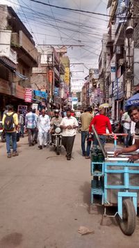
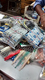
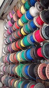
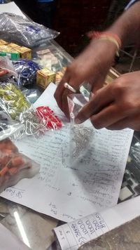
As soon as we entered the lanes, all I could see was electrical shops. There were so many of them and they had almost every electrical component. When we reached Vishal electronics we realized that it is a very busy store and people kept coming and going. There was absolutely no space to even stand. It took like 5-6 hours for them to get all the things from the list and then count each and every component and then negotiate. It was interesting to see so many types of resistors and capacitors, sensors, tools, etc. I had no idea that an electrical shop would be so crowded. There were so many other electrical shops next to each other and to my surprise they had a good rapport with each other. It was really exhausting to just stand there and keep checking. But they patiently got each and every component, although they had to attend so many customers at once. It was a different experience to look around and understand how things worked, but very exhausting and irritating at a certain point.
Intro to Components
Mini project: Lemon battery
I was absent for this class, but I tried this experiment at home. I had absolutely no idea that a lemon or a citrus fruit could be used to make a battery because of the citric acid. So for this battery to work, we used copper wire (cathode) and a galvanized (coated with zinc) nail (anode). Once, the copper wire and the nail were inserted in the lemon and connected through wires, the LED did not light up because the voltage that was received wasn’t enough for the LED to light up. Through this project, I learnt how the process of electrolysis takes place.
Resistors
Fixed Resistors
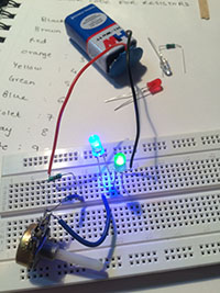
Since I didn’t study physics much, I didn’t know what exactly resistors do. After experimenting with it, I understood it uses. I remembered few things that I had learnt in 9th and 10th std about parallel and series connections. I learnt that resistors help control the voltage that passes in the circuit. So we used an LED to understand this. The brightness and dimness of the LED depends on the resistor that is being used. Working with a breadboard was very convenient and great to work with.
Variable Resistors
Potentiometer, Thermistor and LDR
Working with these components was a really good experience. Potentiometer was something that we actually use in our everyday life, and I had no idea about it. It was very engaging. Thermistor was something that I had never seen or heard of before. Since we had attached a speaker to the connection, we could hear the variations as and when we heated the thermistor. I found it really amusing. LDR for me was very extraordinary. I really liked the way it worked and the fact that we can use it in numerous different ways, in different products. I loved working with this component.
Capacitors and diodes
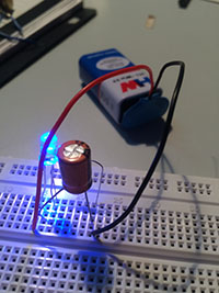
Capacitors and diodes were another fun components to work with. It’s fascinating to understand how these tiny components can do such amazing things. I learnt that capacitors store energy in them, which can be utilised later. Capacitors of different values can be used according to the requirement. At first I didn't understand what a diode does exactly, but later I realised that it actually allows the current to flow in one direction. We even tried placing it the other way round, but the current did not flow. So for it to start flowing again, we took a piece of wire and touched it to the diode's legs, which led the current to flow again to the LED.
Transistor
Touch switch
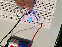
This experiment was very interesting. Touching completed the circuit. As soon as we touched each other or held hands (holding one end of the wire with the other hand) the circuit was completed and the LED lit up. That is when I learnt that our body has some resistance due to which the current started flowing from the body to the LED. It was quite captivating.
555 Oscillator
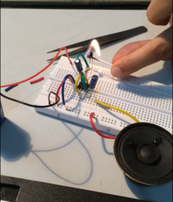
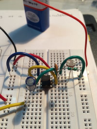
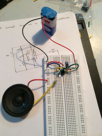
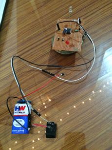
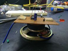
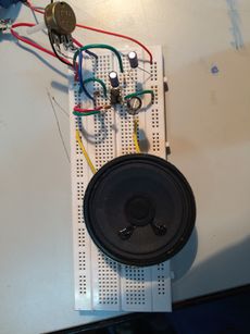
IC was something very different to work with. Every leg had a different connection. Building the circuit on the breadboard was a little difficult for me since I didn’t understand the connection at first. We attached a speaker and it started making amusing sounds. We tried changing the values of the capacitors and resistors and the sounds kept changing accordingly. Attaching an LDR made it even more interesting as it made funny sounds.
PROJECTS
Toy
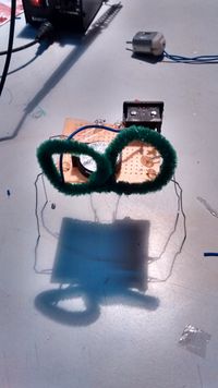
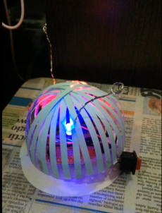
So we had to make a toy using any of the components that we worked with in the first week. So I thought of incorporating all the components. I tried to make a toy, which looked something like a spaceship. I used a speaker at the base for it to make noises. For this I used the 555 IC. Since I wanted it to vibrate and movie, I used the small motor. I also, used an LED and also an LDR. Because of the LDR the sound changed as and when I placed my hand over it. Also, the LED gave it a different look. It was really hard to figure out the connections and it was very time consuming. Soldering it was also very frustrating and it took ages. But fortunately it worked out the way I wanted it to, so I was pretty happy with it.
Amplifier
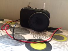
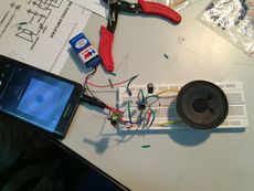
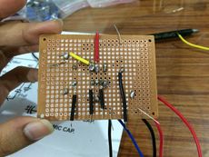
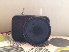
I was really excited for this assignment, learning this meant I could make my own amplifier at home. So in class we made the connections on the breadboard by looking at the diagrams that were given to us. It was a bit confusing but it happened pretty quickly. We used the LM386 for this. It’s amazing to see that such a tiny piece can do wonders.We attached the speaker and the audio jack to the breadboard, and also a potentiometer to vary the sound. It was very exciting when it actually started working when we connected our phones to it. The hard part was when we had to solder all of this on the PCB. It took too much to solder everything as I kept rechecking the placements again and again. When everything was soldered, I switched it on, but it didn’t work at first. Later, after playing around with the wires, I realised that my switch was burnt because of the soldering. Fortunately the circuit worked perfectly fine. For the covering, I thought of making a camera like structure, the old tiny ones. So the speaker resembled the lens part. I had fun to working with this project; also I learnt a lot of things.
Beating Paper
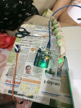
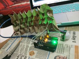
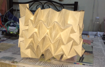
This one was very difficult. Firstly it was so vague that we couldn’t understand how to start. We started brainstorming and got a few ideas. We wanted to work with the color sensor, motion sensor and servo motor. We kept trying to connect these sensors together but we wouldn’t understand how to do it. We finally settled onto one idea, and that was the beating paper. We used servomotor and motion sensor for this. It was really difficult to understand the connections at first, and we kept searching on the Internet. Also, the programming part got annoying since we didn’t really learn it before. So after spending hours and hours to figure out the connections it finally started working. It wasn’t exactly how we wanted it to work, but close enough. So after placing everything inside the box and after tessellating the paper, we connected the servomotor to the paper with thread. It worked pretty well. Although, we had a lot of difficulties through out, it was fun to tackle them down. So the end result was that, it was a paper that beats!
