Difference between revisions of "Shravan"
From (art)scienceblr
(→555 Oscillator) |
(→Making a toy) |
||
| Line 1: | Line 1: | ||
| + | == '''Day1: Creating a Robot''' == | ||
| + | |||
| + | |||
| + | [[File:Robot.jpg|200px|thumb|left|Robot]]It was a lively task making our own robots. Working on soldering, circuits and a few other basic components was really interesting as I felt that the Science textbooks were finally being put to use. The robots were tiny and vibrated due to the motor attached. They performed random motion and looked like an insect after the addition of legs made of wire. | ||
| + | |||
| + | |||
| + | |||
| + | |||
| + | |||
| + | |||
| + | |||
| + | |||
| + | |||
| + | |||
| + | |||
| + | |||
| + | |||
| + | |||
| + | |||
| + | |||
| + | |||
| + | |||
| + | |||
| + | |||
| + | |||
| + | |||
| + | |||
| + | == '''Trip to SP Road''' == | ||
| + | |||
| + | [[File:SP Road.JPG|200px|thumb|left|Vendors and hawkers for tools and equipments.]] The trip was a weary one. There is a constant buzz around and people never seem to stop there. The streets are narrow and workers carrying long steel rods and other cartons full of electronics always kept me on the move. It was amusing to see the vast variety available in each component. The entire shop looked as if it was of miniscule toys. [[File:Vishal Electronics.JPG|200px|thumb|right|Vishal Electronics.]] | ||
| + | |||
| + | |||
| + | |||
| + | |||
| + | |||
| + | |||
| + | |||
| + | |||
| + | |||
| + | |||
| + | |||
| + | |||
| + | |||
| + | |||
| + | |||
| + | |||
| + | |||
| + | |||
| + | |||
| + | |||
| + | |||
| + | |||
| + | |||
| + | |||
| + | == '''Lighting up a LED using Potentiometer''' == | ||
| + | [[File:Potentiometer.JPG|200px|thumb|right|Lit up LED]] Letting variable resistance to pass through the circuit was possible by the use of a Potentiometer. The intensity of the light varied in accordance with the Potentiometer. Reading the circuit diagrams was easy. The breadboard was a fascinating piece. It made work easier as no soldering was required on it and the circuit would be completed even with the slightest contact. Potentiometer is an essential device which saved the LED from getting damaged by not letting excessive current flow. | ||
| + | |||
| + | |||
| + | |||
| + | |||
| + | |||
| + | |||
| + | |||
| + | |||
| + | |||
| + | |||
| + | |||
| + | |||
| + | |||
| + | |||
| + | == '''Capacitor and LED''' == | ||
| + | [[File:IMG 4806.JPG|200px|thumb|left]] The capacitor looks like a mini water tank with legs. Adding a capacitor to the circuit, the LED goes off slowly. The capacitor acts like a small battery storage and lets the current flow through the circuit even after the battery is disconnected. Capacitors of various values can be used to get the desired result. The duration in which the LED turns off differs as capacitors of different values are connected. The link for the video showing the circuit is [[https://youtu.be/Tz5iX3PLg64]] | ||
| + | |||
| + | |||
| + | |||
| + | |||
| + | |||
| + | |||
| + | |||
| + | |||
| + | |||
| + | |||
| + | |||
| + | |||
| + | == Resistors == | ||
| + | |||
| + | |||
| + | === Fixed Resistor === | ||
| + | [[File:IMG 4812.JPG|200px|thumb|left|Normal Resistor]] | ||
| + | |||
| + | |||
| + | |||
| + | |||
| + | |||
| + | |||
| + | |||
| + | |||
| + | |||
| + | |||
| + | |||
| + | |||
| + | |||
| + | |||
| + | |||
| + | |||
| + | |||
| + | === Variable Resistor === | ||
| + | [[File:IMG 4802.JPG|200px|thumb|left|Potentiometer]] | ||
| + | |||
| + | |||
| + | |||
| + | |||
| + | |||
| + | |||
| + | |||
| + | |||
| + | |||
| + | |||
| + | |||
| + | |||
| + | |||
| + | |||
| + | |||
| + | |||
| + | |||
| + | |||
| + | |||
| + | |||
| + | === LDR and Transistor === | ||
| + | [[File:IMG 4836.JPG|200px|thumb|left]] | ||
| + | |||
| + | |||
| + | |||
| + | |||
| + | |||
| + | |||
| + | |||
| + | |||
| + | |||
| + | |||
| + | |||
| + | |||
| + | |||
| + | |||
| + | |||
| + | |||
| + | |||
| + | |||
| + | |||
| + | == 555 Oscillator == | ||
| + | [[File:IMG 4848.JPG|200px|thumb|left]] | ||
| + | |||
| + | |||
| + | |||
| + | |||
| + | |||
| + | |||
| + | |||
| + | |||
| + | |||
| + | |||
| + | |||
| + | |||
| + | |||
| + | |||
| + | |||
| + | |||
| + | |||
== '''Day1: Creating a Robot''' == | == '''Day1: Creating a Robot''' == | ||
| Line 169: | Line 337: | ||
== Making a toy == | == Making a toy == | ||
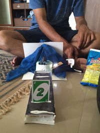
[[File:IMG 4926.JPG|200px|thumb|right]]A lot of thought had to be applied when it came to making a toy. A few toys look simple but the electronics behind it is quite complicated. I merged the idea of a toy and a kinetic sculpture. Using the lower half of a can for rotation with a motor, I attached strings with paper. With the switch kept ON, the toy makes patterns due to the rotation of the colored paper bits. It was actually an eye opener that the toys I bought in my childhood are not that difficult to create at home. | [[File:IMG 4926.JPG|200px|thumb|right]]A lot of thought had to be applied when it came to making a toy. A few toys look simple but the electronics behind it is quite complicated. I merged the idea of a toy and a kinetic sculpture. Using the lower half of a can for rotation with a motor, I attached strings with paper. With the switch kept ON, the toy makes patterns due to the rotation of the colored paper bits. It was actually an eye opener that the toys I bought in my childhood are not that difficult to create at home. | ||
| + | |||
| + | |||
| + | |||
| + | |||
| + | |||
| + | |||
| + | |||
| + | |||
| + | |||
| + | |||
| + | |||
| + | |||
| + | |||
| + | |||
| + | |||
| + | |||
| + | |||
| + | |||
| + | == Amplifier == | ||
| + | Reading the circuit diagram and getting the connections right was a lot of work. It was also frustrating when others were already done with the assignment. After cross checking between the diagram and the actual circuit I could figure out what's wrong. I was amused by the alien sounds that were created when connected with different capacitors. The LM386 looked like a 8 legged spider which made the connections increase in number and complexity.[[File:IMG 4930.JPG|200px|thumb|left|Connected Circuit]] | ||
| + | |||
| + | |||
| + | |||
| + | |||
| + | |||
| + | |||
| + | |||
| + | |||
| + | |||
| + | |||
| + | |||
| + | |||
| + | |||
| + | |||
| + | |||
| + | |||
| + | |||
| + | |||
| + | |||
| + | |||
| + | |||
| + | |||
| + | |||
| + | |||
| + | == Speaker == | ||
| + | Making our own working speakers,the assignment was a fun process. I chose a cardboard box and made a few modifications to keep the phone and for easy volume adjustment. [[File:IMG 5072.JPG|200px|thumb|right|Final Product]] | ||
| + | The working of the speaker is shown in the video [[https://youtu.be/AqU4m6c4DzI]] | ||
| + | |||
| + | |||
| + | |||
| + | |||
| + | |||
| + | |||
| + | |||
| + | |||
| + | |||
| + | |||
| + | |||
| + | |||
| + | |||
| + | |||
| + | |||
| + | |||
| + | |||
| + | |||
| + | |||
| + | |||
| + | |||
| + | |||
| + | |||
| + | |||
| + | == Arduino == | ||
| + | |||
| + | |||
| + | === Blinking a LED === | ||
| + | It was my first time working with an Arduino board. I got accustomed to the few basic syntax rules as they were direct and coherent. Blinking a LED using Arduino, controlling the delay and also, controlling it with the LDR were simple tasks with simple commands. [[File:IMG 4947.JPG|200px|thumb|left]] Later, we also managed to connect a motor with the Arduino and controlled it with a LDR. The link for the video [[https://youtu.be/cE7vmzpP8Qw]] | ||
| + | |||
| + | |||
| + | |||
| + | |||
| + | |||
| + | |||
| + | |||
| + | |||
| + | |||
| + | |||
| + | |||
| + | |||
| + | |||
| + | |||
| + | |||
| + | === Knight Rider === | ||
| + | By looking at the original video for Knight Rider, I thought that it was next to impossible to replicate the same effects. But soon enough as I started working on it, it was actually easy. The link for the video [[https://youtu.be/ijXYxlhmU0A]] [[File:IMG 4956.JPG|200px|thumb|center]] | ||
| + | |||
| + | |||
| + | |||
| + | |||
| + | |||
| + | |||
| + | |||
| + | |||
| + | |||
| + | |||
| + | |||
| + | === Magic Man === | ||
| + | I was working in a group with Rajat and Mizba. I did not want to limit myself by doing only a particular task. Hence, I tried helping in all the stages; ideation, design, coding, making the body and connections, etc. UV sensor has a lot of varied uses for practical purposes. But we had to come up with an object that did something magical. We did a card trick in which the number on the card wpuld be represented by the number of flashing LEDs on the magician's hand. [[File:IMG 5118.JPG|200px|thumb|left]] To see the magic man's video, [[https://youtu.be/4xnrQ6AdBUY]] | ||
Revision as of 14:17, 18 October 2015
Contents
- 1 Day1: Creating a Robot
- 2 Trip to SP Road
- 3 Lighting up a LED using Potentiometer
- 4 Capacitor and LED
- 5 Resistors
- 6 555 Oscillator
- 7 Day1: Creating a Robot
- 8 Trip to SP Road
- 9 Lighting up a LED using Potentiometer
- 10 Capacitor and LED
- 11 Resistors
- 12 555 Oscillator
- 13 Making a toy
- 14 Amplifier
- 15 Speaker
- 16 Arduino
Day1: Creating a Robot
It was a lively task making our own robots. Working on soldering, circuits and a few other basic components was really interesting as I felt that the Science textbooks were finally being put to use. The robots were tiny and vibrated due to the motor attached. They performed random motion and looked like an insect after the addition of legs made of wire.
Trip to SP Road
The trip was a weary one. There is a constant buzz around and people never seem to stop there. The streets are narrow and workers carrying long steel rods and other cartons full of electronics always kept me on the move. It was amusing to see the vast variety available in each component. The entire shop looked as if it was of miniscule toys.
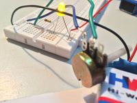
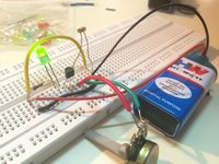
Lighting up a LED using Potentiometer
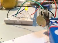
Letting variable resistance to pass through the circuit was possible by the use of a Potentiometer. The intensity of the light varied in accordance with the Potentiometer. Reading the circuit diagrams was easy. The breadboard was a fascinating piece. It made work easier as no soldering was required on it and the circuit would be completed even with the slightest contact. Potentiometer is an essential device which saved the LED from getting damaged by not letting excessive current flow.
Capacitor and LED
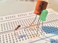
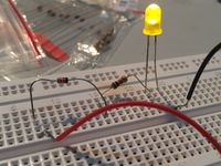
The capacitor looks like a mini water tank with legs. Adding a capacitor to the circuit, the LED goes off slowly. The capacitor acts like a small battery storage and lets the current flow through the circuit even after the battery is disconnected. Capacitors of various values can be used to get the desired result. The duration in which the LED turns off differs as capacitors of different values are connected. The link for the video showing the circuit is [[1]]
Resistors
Fixed Resistor
Variable Resistor
LDR and Transistor
555 Oscillator
Day1: Creating a Robot
It was a lively task making our own robots. Working on soldering, circuits and a few other basic components was really interesting as I felt that the Science textbooks were finally being put to use. The robots were tiny and vibrated due to the motor attached. They performed random motion and looked like an insect after the addition of legs made of wire.
Trip to SP Road
The trip was a weary one. There is a constant buzz around and people never seem to stop there. The streets are narrow and workers carrying long steel rods and other cartons full of electronics always kept me on the move. It was amusing to see the vast variety available in each component. The entire shop looked as if it was of miniscule toys.
Lighting up a LED using Potentiometer
Letting variable resistance to pass through the circuit was possible by the use of a Potentiometer. The intensity of the light varied in accordance with the Potentiometer. Reading the circuit diagrams was easy. The breadboard was a fascinating piece. It made work easier as no soldering was required on it and the circuit would be completed even with the slightest contact. Potentiometer is an essential device which saved the LED from getting damaged by not letting excessive current flow.
Capacitor and LED
The capacitor looks like a mini water tank with legs. Adding a capacitor to the circuit, the LED goes off slowly. The capacitor acts like a small battery storage and lets the current flow through the circuit even after the battery is disconnected. Capacitors of various values can be used to get the desired result. The duration in which the LED turns off differs as capacitors of different values are connected. The link for the video showing the circuit is [[2]]
Resistors
Fixed Resistor
Variable Resistor
LDR and Transistor
555 Oscillator
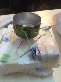
Making a toy
A lot of thought had to be applied when it came to making a toy. A few toys look simple but the electronics behind it is quite complicated. I merged the idea of a toy and a kinetic sculpture. Using the lower half of a can for rotation with a motor, I attached strings with paper. With the switch kept ON, the toy makes patterns due to the rotation of the colored paper bits. It was actually an eye opener that the toys I bought in my childhood are not that difficult to create at home.
Amplifier
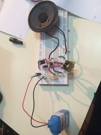
Reading the circuit diagram and getting the connections right was a lot of work. It was also frustrating when others were already done with the assignment. After cross checking between the diagram and the actual circuit I could figure out what's wrong. I was amused by the alien sounds that were created when connected with different capacitors. The LM386 looked like a 8 legged spider which made the connections increase in number and complexity.
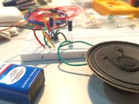
Speaker
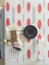
Making our own working speakers,the assignment was a fun process. I chose a cardboard box and made a few modifications to keep the phone and for easy volume adjustment.The working of the speaker is shown in the video [[3]]
Arduino
Blinking a LED
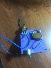
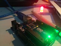
It was my first time working with an Arduino board. I got accustomed to the few basic syntax rules as they were direct and coherent. Blinking a LED using Arduino, controlling the delay and also, controlling it with the LDR were simple tasks with simple commands. Later, we also managed to connect a motor with the Arduino and controlled it with a LDR. The link for the video [[4]]
Knight Rider
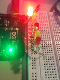
By looking at the original video for Knight Rider, I thought that it was next to impossible to replicate the same effects. But soon enough as I started working on it, it was actually easy. The link for the video [[5]]
