Difference between revisions of "Payal Tanksale"
(→Introduction) |
(→Soldering and LED meter with sensor) |
||
| (30 intermediate revisions by one user not shown) | |||
| Line 10: | Line 10: | ||
In this particular task, we made a creature which works of Arduino Uno, servo motors and IR sensor. While making we face slight problems in the coding and connections of the IR sensor. The coding was going wrong which was difficult to figure out. The serial number reading wasn’t changing from zero. Also the coding at the point when we had to synchronize the two motors and add in values accordingly. | In this particular task, we made a creature which works of Arduino Uno, servo motors and IR sensor. While making we face slight problems in the coding and connections of the IR sensor. The coding was going wrong which was difficult to figure out. The serial number reading wasn’t changing from zero. Also the coding at the point when we had to synchronize the two motors and add in values accordingly. | ||
Overall it was a good revision to the previous sessions as I realized while doing that there were many things I had forgotten about. Though a quick throwback, I kind of can now relate to the equipment and figure out a little coding as well. | Overall it was a good revision to the previous sessions as I realized while doing that there were many things I had forgotten about. Though a quick throwback, I kind of can now relate to the equipment and figure out a little coding as well. | ||
| + | |||
| + | [[File:New 4.JPG|300px]] | ||
| + | |||
| + | =Resistors in Series and Parallel= | ||
| + | ==Resistors in Series== | ||
| + | |||
| + | Consider two resistors R1 and R2 | ||
| + | Voltage V | ||
| + | Current I | ||
| + | |||
| + | The current flowing I will be opposed by two resistances. The equivalent resistance will be the sum of the individual resistance. If current flows through R1 and R2 the voltage will drop at those two points. | ||
| + | By Ohm’s Law, | ||
| + | V1= IR1, V2=IR2 | ||
| + | |||
| + | Total Voltage V= V1+V2 | ||
| + | |||
| + | V=IR1+IR2 | ||
| + | |||
| + | V=I(R1+R2) | ||
| + | |||
| + | V/I=R1+R2 | ||
| + | |||
| + | But=IR | ||
| + | |||
| + | IR/I=R1+R2 | ||
| + | |||
| + | R=R1+R2 | ||
| + | |||
| + | ==Resistors in Parallel== | ||
| + | |||
| + | Consider resistance R1 and R2. | ||
| + | Voltage V | ||
| + | Current I | ||
| + | Here the current gets divided by the two resistance connected in parallel. | ||
| + | Therefore total current (I) = I1+I2 | ||
| + | By Ohm’s Law, | ||
| + | |||
| + | V=IR | ||
| + | |||
| + | Therefore, I=V/R | ||
| + | |||
| + | Substituting in the equation, | ||
| + | |||
| + | I= V/R1+V/R2 | ||
| + | |||
| + | I=V(1/R1+1/R2) | ||
| + | |||
| + | V/R=V(1/R1+1/R2) | ||
| + | |||
| + | 1/R=1/R1+1/R2 | ||
| + | |||
| + | ==Reflection== | ||
| + | The first half of the class was a basic introduction to the necessary terms. It was again a revision oh what we learnt in our physics class. It now can relate to the fact how these equations play a vital role in building the circuits. I remember how once we had shot the LED while we were working with the revision project as we forgot to apply a certain Ohm resistor to the circuit. I am looking forward in learning the conversions as I feel I am kind of lacking I the basics. | ||
| + | |||
| + | The second half was really fun. It was good experience to visit the place and collect samples. We collected around 8 samples from different areas. Some with clear water some with algae and some with moss and rainwater puddles. We also have taken soil samples. The place had a peculiar smell in the beginning like too many harmful gases were mixed together. Also, the place was dumped with a lot of waste. In spite of this there were a lot of birds wandering around the lake which gives a clue of there being fishes or some food they rely on. We found some water creatures as well which can gives us an idea about the clarity of the water. Looking forward to understand the organisms and what role they play and how can we relate sensors to these creatures. | ||
| + | |||
| + | [[File:WhatsApp Image 2017-03-14 at 12.10.07 PM.jpeg|200px]] [[File:WhatsApp Image 2017-03-14 at 12.10.01 PM.jpeg|200px]] [[File:WhatsApp Image 2017-03-14 at 12.10.06 PM.jpeg|200px]] | ||
| + | |||
| + | =Air Quality Sensor= | ||
| + | |||
| + | Develop a Air quality sensor. | ||
| + | |||
| + | ==Circuit== | ||
| + | |||
| + | [[File:Mq135pins.jpg]] | ||
| + | |||
| + | ==Connections== | ||
| + | |||
| + | [[File:WhatsApp Image 2017-03-14 at 4.36.13 PM.jpeg|500px]] | ||
| + | |||
| + | ==Coding== | ||
| + | |||
| + | [[File:Screenshot (82).png|500px]] | ||
| + | |||
| + | ==Reflection== | ||
| + | |||
| + | It was a good learning experience as I learnt a little more about Arduino coding. Initially the coding was going wrong as I had not entered the correct analogue pin number. I was able to understand the connections and the pins of the sensor. | ||
| + | |||
| + | =Turbidity Sensor= | ||
| + | |||
| + | Developed your own turbidity sensor. | ||
| + | |||
| + | [[File:IMG 20170310 102825.jpg|200px]] [[File:IMG 20170310 101830.jpg|200px]] [[File:IMG 20170310 101851.jpg|200px]] | ||
| + | [[File:IMG 20170310 105520.jpg|200px]] [[File:IMG 20170310 133237.jpg|200px]] | ||
| + | |||
| + | ==Circuit== | ||
| + | |||
| + | [[File:LDR circuit.png|300px]] | ||
| + | |||
| + | ==Connections== | ||
| + | |||
| + | [[File:IMG 20170310 101908.jpg|300px]] [[File:LDR1-1-620x436.png|300px]] | ||
| + | |||
| + | ==Coding== | ||
| + | |||
| + | [[File:Screenshot (109).png|400px]] | ||
| + | |||
| + | ==Graph== | ||
| + | |||
| + | [[File:ChartGo (grid).png|400px]] | ||
| + | |||
| + | ==Reflection== | ||
| + | |||
| + | Building your own sensor felt like some achievement. Initially I was kind of worried how we build our own sensor. After understanding the connections it seemed easy as it was based on a LDR which we had studied before. After the connections we tested it and it worked fine. Later we placed it in the box it started misbehaving. I wasn’t able to understand | ||
| + | what went wrong. Later after some time I realized I had done the connection wrong while reconnecting while placing in the box. We tested it with samples and it worked fine. A slightest change of pin made a huge difference to the working. It was interesting to learn making of such sensors as the huge machines are built on the base of such a small connection. | ||
| + | |||
| + | =Futuristic thinking= | ||
| + | |||
| + | == Draw Cyborg, Post Human== | ||
| + | |||
| + | For Cyborg I drew a human which has a robotic head and a normal human body. The body functions like a human but the thinking and the working of the brain is robot. Basically can be controlled. For post human, initially I drew a weirdly looking creature but later I drew soil particles which shows the disappearance of the human race. | ||
| + | |||
| + | [[File:WhatsApp Image 2017-03-14 at 12.09.59 PM.jpeg|200px]] | ||
| + | |||
| + | ==Futuristic Gadget== | ||
| + | |||
| + | For this particular task, I was paired with Aman. We made a head gear which had an antenna which could read everyone's mind. Also, the headgear had a mic which can be used to talk of things which a person wants the other people to obey or listen. | ||
| + | |||
| + | [[File:WhatsApp Image 2017-03-14 at 9.59.32 PM.jpeg|200px]] | ||
| + | |||
| + | =Line Graph with d3= | ||
| + | |||
| + | Construct a line graph using d3. | ||
| + | |||
| + | [[File:Screenshot (132).png|400px]] [[File:Screenshot (134).png|400px]] | ||
| + | |||
| + | ==Reflection== | ||
| + | |||
| + | It was huge task getting the output. I haven't done any language coding in school. I am absolutely unaware of the basic and thats why I found it difficult to understand. I began with reading come codes online so as to know how its done but then it seemed to be very confusing. After a point I tried entering data and saw how the code changes and figured out a part of it. Getting the x axis was something I was suck on but then got the doubt cleared. I can conclude saying I would have learnt a percent of it. It would have been easier, if I knew some basic terms and would have been a faster learning. | ||
| + | |||
| + | [[File:Screenshot (132).png|400px]] [[File:Screenshot (134).png|400px]] | ||
| + | |||
| + | =Arduino with Processing= | ||
| + | |||
| + | In this task we had to give output of the Arduino data in graphical form which shows the change in values by wave graph.This seemed easy to understand. How to link one programme to the other and use processing to give out the output data. | ||
| + | |||
| + | [[File:Screenshot (145).png|350px]] [[File:Screenshot (142).png|350px]] [[File:Screenshot (143).png|350px]] | ||
| + | |||
| + | =Blink the LED Tasks= | ||
| + | |||
| + | ==Blink the LED 5 times only== | ||
| + | |||
| + | [[File:Screenshot (159).png|400px]] | ||
| + | |||
| + | ==Let the Serial monitor ask number of times== | ||
| + | |||
| + | [[File:Screenshot (168).png|400px]] [[File:Screenshot (166).png|400px]] | ||
| + | |||
| + | ==LDR value decides the blinking== | ||
| + | |||
| + | [[File:Screenshot (173).png|400px]] [[File:Screenshot (171).png|400px]] | ||
| + | |||
| + | ==Reflection== | ||
| + | |||
| + | Today, I really could understand coding correctly. It was really easy to understand as we tried to code from first writing in simple english and then converting it into code language.Similarly, for the circuits, using logic for the connections. Why input and output values are used etc. I feel I have much better understanding with this particular writing and rewriting the code now. | ||
| + | |||
| + | =LED meter= | ||
| + | |||
| + | ==Soldering and LED meter with sensor(LDR)== | ||
| + | |||
| + | [[File:WhatsApp Image 2017-03-24 at 9.17.38 PM.jpeg|200px]] [[File:WhatsApp Image 2017-03-24 at 9.17.39 PM.jpeg|200px]] [[File:WhatsApp Image 2017-04-09 at 2.25.30 PM.jpeg|200px]] | ||
| + | |||
| + | ==EMF== | ||
| + | |||
| + | [[File:WhatsApp Image 2017-04-09 at 3.05.31 PM.jpeg|300px]] | ||
| + | |||
| + | =Final Project (Self watering Plant)= | ||
| + | |||
| + | Equipments used | ||
| + | |||
| + | Arduino<br> | ||
| + | Servo Motor<br> | ||
| + | Soil sensor<br> | ||
| + | |||
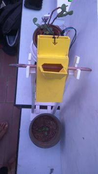
| + | This task was based on a simple concept where we talk for the plants. We as humans decide the amount of water required for them to survive. Instead we thought why not the plant decide for itself when it wants to have water and then accordingly water itself.We had a secondary idea of adding a voice where the plants talks to the user about the activity been performed. We had the codes running individually for both the circuits but wasn't working out when we tried combining them. We kind of could figure out where we went wrong but then it wast functioning the way we wanted to. I learnt the linking of programs and now have a better understanding of the for loops. | ||
| + | |||
| + | |||
| + | [[File:WhatsApp Image 2017-04-09 at 2.25.32 PM.jpeg|300px]] [[File:WhatsApp Image 2017-04-08 at 6.41.20 PM (1).jpeg|300px ]] [[File: WhatsApp Image 2017-04-08 at 6.41.14 PM.jpeg|200px]] [[File:WhatsApp Image 2017-04-08 at 6.41.15 PM.jpeg|200px]] | ||
Latest revision as of 15:59, 9 April 2017
Contents
Introduction
About me
Hello, my name is Payal. I am studying Industrial Arts and Design practices at Srishti Institute of Art, Design and Technology. I have developed interest in electronics since the last sensors class. I have made tiny circuits for different projects in my products and I feel I can reflect some of my electronic learning in further projects as well. Learning Arduino coding was kind of difficult for me initially hence, this class I am looking forward to get hand of the Arduino and explore more sensors.
Touch me not monster
Reflection
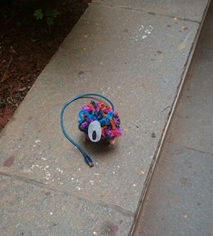
In this particular task, we made a creature which works of Arduino Uno, servo motors and IR sensor. While making we face slight problems in the coding and connections of the IR sensor. The coding was going wrong which was difficult to figure out. The serial number reading wasn’t changing from zero. Also the coding at the point when we had to synchronize the two motors and add in values accordingly. Overall it was a good revision to the previous sessions as I realized while doing that there were many things I had forgotten about. Though a quick throwback, I kind of can now relate to the equipment and figure out a little coding as well.
Resistors in Series and Parallel
Resistors in Series
Consider two resistors R1 and R2 Voltage V Current I
The current flowing I will be opposed by two resistances. The equivalent resistance will be the sum of the individual resistance. If current flows through R1 and R2 the voltage will drop at those two points. By Ohm’s Law, V1= IR1, V2=IR2
Total Voltage V= V1+V2
V=IR1+IR2
V=I(R1+R2)
V/I=R1+R2
But=IR
IR/I=R1+R2
R=R1+R2
Resistors in Parallel
Consider resistance R1 and R2. Voltage V Current I Here the current gets divided by the two resistance connected in parallel. Therefore total current (I) = I1+I2 By Ohm’s Law,
V=IR
Therefore, I=V/R
Substituting in the equation,
I= V/R1+V/R2
I=V(1/R1+1/R2)
V/R=V(1/R1+1/R2)
1/R=1/R1+1/R2
Reflection
The first half of the class was a basic introduction to the necessary terms. It was again a revision oh what we learnt in our physics class. It now can relate to the fact how these equations play a vital role in building the circuits. I remember how once we had shot the LED while we were working with the revision project as we forgot to apply a certain Ohm resistor to the circuit. I am looking forward in learning the conversions as I feel I am kind of lacking I the basics.
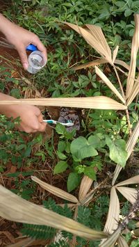
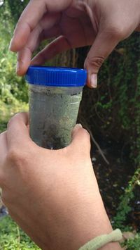
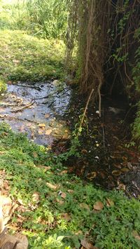
The second half was really fun. It was good experience to visit the place and collect samples. We collected around 8 samples from different areas. Some with clear water some with algae and some with moss and rainwater puddles. We also have taken soil samples. The place had a peculiar smell in the beginning like too many harmful gases were mixed together. Also, the place was dumped with a lot of waste. In spite of this there were a lot of birds wandering around the lake which gives a clue of there being fishes or some food they rely on. We found some water creatures as well which can gives us an idea about the clarity of the water. Looking forward to understand the organisms and what role they play and how can we relate sensors to these creatures.
Air Quality Sensor
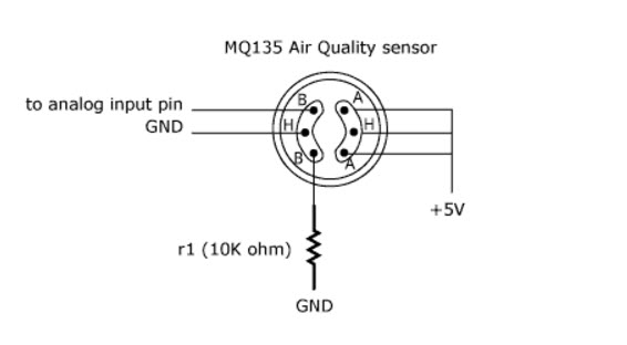
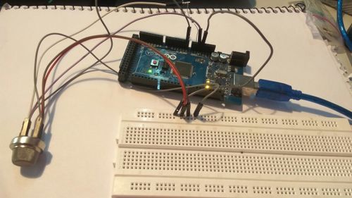
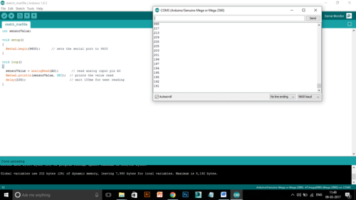
Develop a Air quality sensor.
Circuit
Connections
Coding
Reflection
It was a good learning experience as I learnt a little more about Arduino coding. Initially the coding was going wrong as I had not entered the correct analogue pin number. I was able to understand the connections and the pins of the sensor.
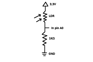
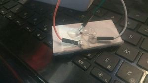
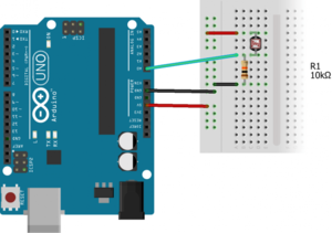
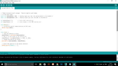
Turbidity Sensor
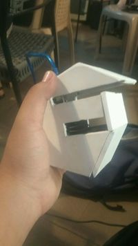
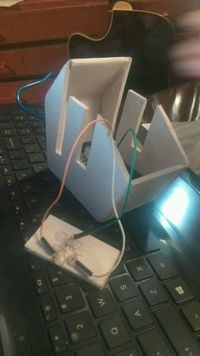
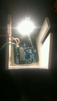
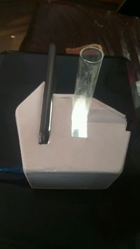
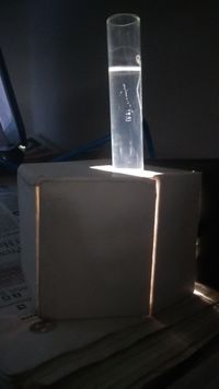
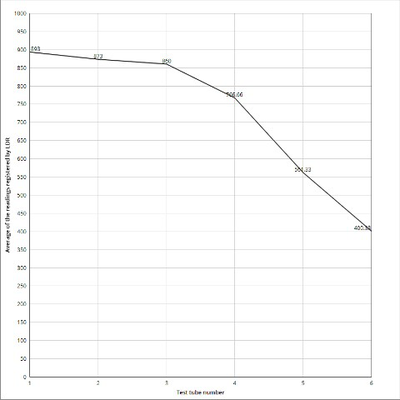
Developed your own turbidity sensor.
Circuit
Connections
Coding
Graph
Reflection
Building your own sensor felt like some achievement. Initially I was kind of worried how we build our own sensor. After understanding the connections it seemed easy as it was based on a LDR which we had studied before. After the connections we tested it and it worked fine. Later we placed it in the box it started misbehaving. I wasn’t able to understand what went wrong. Later after some time I realized I had done the connection wrong while reconnecting while placing in the box. We tested it with samples and it worked fine. A slightest change of pin made a huge difference to the working. It was interesting to learn making of such sensors as the huge machines are built on the base of such a small connection.
Futuristic thinking
Draw Cyborg, Post Human
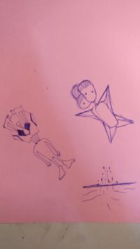
For Cyborg I drew a human which has a robotic head and a normal human body. The body functions like a human but the thinking and the working of the brain is robot. Basically can be controlled. For post human, initially I drew a weirdly looking creature but later I drew soil particles which shows the disappearance of the human race.
Futuristic Gadget
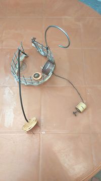
For this particular task, I was paired with Aman. We made a head gear which had an antenna which could read everyone's mind. Also, the headgear had a mic which can be used to talk of things which a person wants the other people to obey or listen.
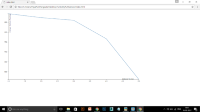
Line Graph with d3
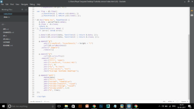
Construct a line graph using d3.
Reflection
It was huge task getting the output. I haven't done any language coding in school. I am absolutely unaware of the basic and thats why I found it difficult to understand. I began with reading come codes online so as to know how its done but then it seemed to be very confusing. After a point I tried entering data and saw how the code changes and figured out a part of it. Getting the x axis was something I was suck on but then got the doubt cleared. I can conclude saying I would have learnt a percent of it. It would have been easier, if I knew some basic terms and would have been a faster learning.
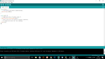
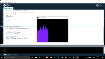
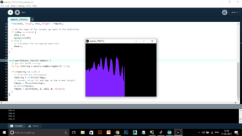
Arduino with Processing
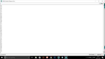
In this task we had to give output of the Arduino data in graphical form which shows the change in values by wave graph.This seemed easy to understand. How to link one programme to the other and use processing to give out the output data.
Blink the LED Tasks
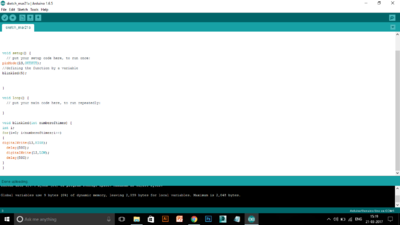
Blink the LED 5 times only
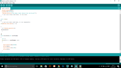
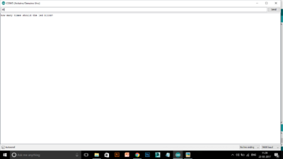
Let the Serial monitor ask number of times
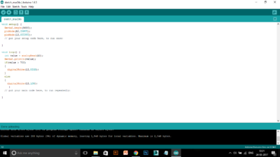
LDR value decides the blinking
Reflection
Today, I really could understand coding correctly. It was really easy to understand as we tried to code from first writing in simple english and then converting it into code language.Similarly, for the circuits, using logic for the connections. Why input and output values are used etc. I feel I have much better understanding with this particular writing and rewriting the code now.
LED meter
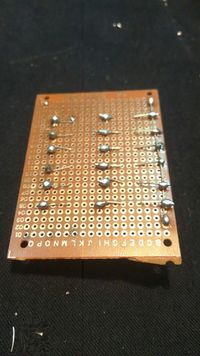
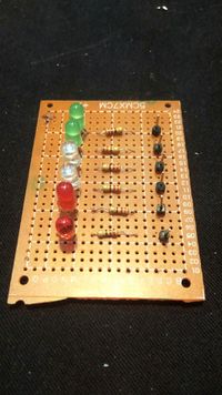
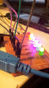
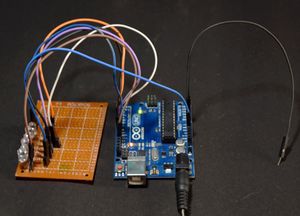
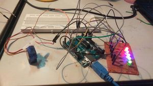
Soldering and LED meter with sensor(LDR)
EMF
Final Project (Self watering Plant)
Equipments used
Arduino
Servo Motor
Soil sensor
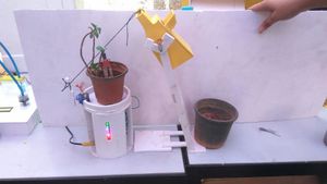
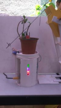
This task was based on a simple concept where we talk for the plants. We as humans decide the amount of water required for them to survive. Instead we thought why not the plant decide for itself when it wants to have water and then accordingly water itself.We had a secondary idea of adding a voice where the plants talks to the user about the activity been performed. We had the codes running individually for both the circuits but wasn't working out when we tried combining them. We kind of could figure out where we went wrong but then it wast functioning the way we wanted to. I learnt the linking of programs and now have a better understanding of the for loops.
