Difference between revisions of "Mizba"
| (16 intermediate revisions by one user not shown) | |||
| Line 4: | Line 4: | ||
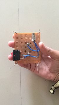
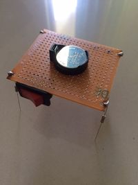
Day 1 of Sensors, Probes and Detectors. I was extremely excited. My facilitator, Yashas, only tells us all that we were going to build a robot. And I was a little nervous. I had absolutely no prior know-abouts regarding Electronics, except in school though. What I had studied in school was already hazy and I couldn’t contain my excitement, on day one of this class, in anticipation of learning an entirely new subject. This was my first experience with learning how to solder. Truth be told, mine was the worst kind of soldering in the class. Although, eventually, I got the hang of it and now, I absolutely enjoy using the solder iron. We were only given instructions as to the making of a robot. Honestly, I didn't understand much about what I was doing, but I was only following the instructions. I was the last to finish making my robot, but it was not at all in vain. I took time to understand the logic behind why we did what we did. That was a fulfilling day, alright. | Day 1 of Sensors, Probes and Detectors. I was extremely excited. My facilitator, Yashas, only tells us all that we were going to build a robot. And I was a little nervous. I had absolutely no prior know-abouts regarding Electronics, except in school though. What I had studied in school was already hazy and I couldn’t contain my excitement, on day one of this class, in anticipation of learning an entirely new subject. This was my first experience with learning how to solder. Truth be told, mine was the worst kind of soldering in the class. Although, eventually, I got the hang of it and now, I absolutely enjoy using the solder iron. We were only given instructions as to the making of a robot. Honestly, I didn't understand much about what I was doing, but I was only following the instructions. I was the last to finish making my robot, but it was not at all in vain. I took time to understand the logic behind why we did what we did. That was a fulfilling day, alright. | ||
| + | |||
| + | |||
| + | |||
| + | |||
| + | |||
| + | |||
| + | |||
| + | |||
| + | |||
| + | |||
| + | '''Lemon Battery''' | ||
| + | |||
| + | [[File:IMG_3580.jpg|200px|thumb|right|Looking for a certain amount of voltage from lemons to light up an LED]] | ||
| + | |||
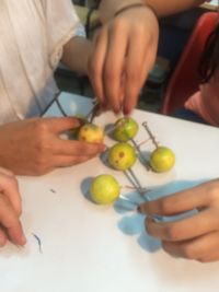
| + | This was our first weekend and it was time for our first weekend homework. When I heard that we were to make a battery out of lemons and light up a LED, I was excited as well as tense as to how I was going to make a lemon battery in the first week itself, without any instructions or any knowledge about Electronics. I resorted to YouTube and found that all it took was a big, raw lemon, a copper wire and a nail. I only thought that it was that easy. When I actually tried it, I faced a lot of trouble acquiring enough voltage to light up the LED. When, finally, in class four of us combined our lemon batteries, we finally got very little voltage enough to let the LED glow very dim. | ||
| + | |||
| + | |||
| + | |||
| + | |||
| + | |||
| + | |||
| + | |||
| + | |||
| + | |||
| + | |||
| + | |||
| + | |||
| + | |||
| + | |||
| + | |||
| + | |||
| + | |||
| + | '''Switch''' | ||
| + | |||
| + | [[File:IMG_3586.jpg|200px|thumb|left|Switch is Off]] [[File:IMG_3587.jpg|200px|thumb|right|Switch is On]] | ||
| + | |||
| + | [[File:IMG_3603.jpg|200px|thumb|left|Switch is Off]] [[File:IMG_3601.jpg|200px|thumb|right|Switch is On]] | ||
| + | |||
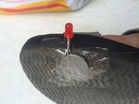
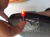
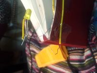
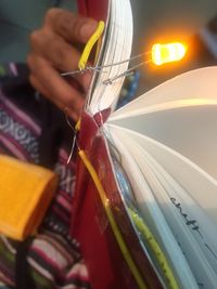
| + | I particularly enjoyed the rate at which the class progressed. Many have complained that it was all going too slow. But on the other hand, I liked the systematic way of teaching in the class. One component per day. Understood well. Especially, for someone like me who needed time to get acquainted with the rules and everything else within the world of electronics. The first component we learnt of was a switch. We all know that a switch, technically, is something that helps us complete any circuit. Now keeping this in mind, we had to make our own switch. We made two types of switches. One, where an LED would light up with pressure put on one loose end of the circuit to sit onto the other end. Basically, we attached this circuit to a slipper, wherein when there is pressure put down by the foot, the LED lights up. The second kind of switch we made was for a book. When the book was opened, the two loose ends of the circuit would meet and thereby, complete the circuit, resulting in the LED lighting up. | ||
| + | |||
| + | |||
| + | |||
| + | |||
| + | |||
| + | |||
| + | |||
| + | |||
| + | |||
| + | |||
| + | |||
| + | |||
| + | |||
| + | |||
| + | |||
| + | |||
| + | |||
| + | |||
| + | |||
| + | '''Breadboard and LEDs''' | ||
| + | |||
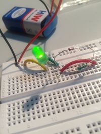
| + | [[File:IMG_3783.jpg|200px|thumb|left|One LED on Breadboard]] [[File:IMG_3791.jpg|150px|thumb|right|Three LEDs on Breadboard]] | ||
| + | |||
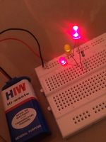
| + | Next, we learned how to use and work on a breadboard. I had never seen a breadboard before, let alone working with one. It took me quite a while to understand how to build circuits on the breadboard. Today, I think breadboards are awesome! I used to see a lot of my classmates work in class like they knew exactly what they were doing and that they already understood what had been explained. I felt out of place for a few days in the beginning because I thought I was the only one who didn't understand too soon. Slowly, I began to cope and my levels of interest rose. The most basic thing to use as an element to understand anything is an LED. Here too, we started with making a very simple circuit by just lighting up an LED. We had to use the 9V batteries for the circuit. Since LEDs cannot sustain 9V, we had to make use of a resistor. When we were good with making the circuit for one LED lighting up we made one with two or three or four LEDs. The basic principle is that an LED has two legs; one longer than the other. The longer leg is connected to ground whereas the shorter leg goes to the positive source. | ||
| + | |||
| + | |||
| + | |||
| + | |||
| + | |||
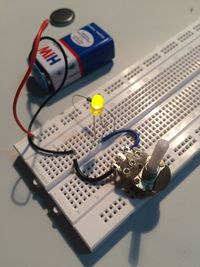
| + | '''Potentiometer''' | ||
| + | |||
| + | [[File:IMG_3815.jpg|200px|thumb|right|10K Pot]] | ||
| + | |||
| + | Along with the lighting of the LEDs, we made use of a new component called a ‘Potentiometer’. I was extremely fascinated by the fact that it is a potentiometer used in music systems to increase or reduce the volume. The potentiometer adjusts the resistance in the circuit and this is what helps in the high/low output. | ||
| + | |||
| + | |||
| + | |||
| + | |||
| + | |||
| + | |||
| + | |||
| + | |||
| + | |||
| + | |||
| + | |||
| + | |||
| + | |||
| + | |||
| + | |||
| + | |||
| + | |||
| + | |||
| + | |||
| + | |||
| + | '''Multimeter''' | ||
| + | |||
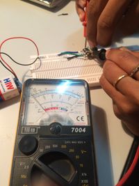
| + | [[File:IMG_3823.jpg|200px|thumb|right|Using A Multimeter To Measure Resistance]] | ||
| + | |||
| + | A multimeter, I learnt, is a measuring device used to measure different kinds of units, which includes Ohms (for measuring the resistance an object has tooffer), Voltage and electric current. These vary over ranging values and are effective in almost every stage of working with electronics. Normally, there are meters to measure only a particular unit. For example, an Ohmmeter, a Voltmeter, etc. A multimeter is portably convenient as well as does the trick for most jobs. | ||
| + | |||
| + | |||
| + | |||
| + | |||
| + | |||
| + | |||
| + | |||
| + | |||
| + | |||
| + | |||
| + | |||
| + | |||
| + | |||
| + | |||
| + | |||
| + | |||
| + | |||
| + | |||
| + | |||
| + | |||
| + | '''Capacitor''' | ||
| + | |||
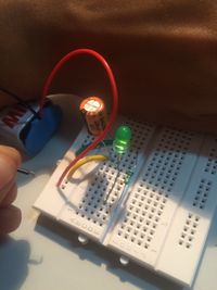
| + | [[File:IMG_3846.jpg|200px|thumb|right|LED glows in a broken circuit with the help of a capacitor]] | ||
| + | |||
| + | A capacitor is an extremely useful component. Although, the ones we have used in class were a little lower in capacitating power, I realise that they are very useful in cases where one doesn't need to connect to a power source. The capacitor stores some amount of energy which can be made use of. It is like a power backup. | ||
| + | |||
| + | |||
| + | |||
| + | |||
| + | |||
| + | |||
| + | |||
| + | |||
| + | |||
| + | |||
| + | |||
| + | |||
| + | |||
| + | |||
| + | |||
| + | |||
| + | |||
| + | |||
| + | |||
| + | |||
| + | |||
| + | |||
| + | '''Diode''' | ||
| + | |||
| + | [[File:IMG_3857.jpg|200px|thumb|right|Diode permits the flow of current in the right direction]] | ||
| + | |||
| + | I must’ve studied of a diode in school, but the memory of that learning had completely washed off. The word ‘diode’ sounded familiar, but I had completely forgotten about its function and use. Understanding that a diode marks the flow of current in only one direction is a refreshing experience. I have received so much joy in understanding the littlest of components of electronics.To someone well-acquainted with electronics this kind of excitement may seem unnecessary. But greater joy comes to me when I understand the 1+2+1+3 and not just 7 as a whole. | ||
| + | |||
| + | |||
| + | |||
| + | |||
| + | |||
| + | |||
| + | |||
| + | |||
| + | |||
| + | |||
| + | |||
| + | |||
| + | |||
| + | |||
| + | |||
| + | |||
| + | |||
| + | |||
| + | |||
| + | '''Transistor''' | ||
| + | |||
| + | [[File:IMG_3866.jpg|200px|thumb|left|Circuit diagram for a transistor]] [[File:IMG_3874.jpg|200px|thumb|right|Transistor with a human switch]] | ||
| + | [[File:IMG_3878.jpg|200px|thumb|left|Transistor+LDR+LED+10K Pot]] [[File:IMG_3884.jpg|200px|thumb|right|Shadow on the LDR makes the LED go off]] | ||
| + | |||
| + | To an electronics guy, a transistor was a legendary innovation. I hadn't known the importance of a transistor up until I heard it through Mr. Bala in this class. Uptil until this far, we were only used to working with components that had two legs. Even though the potentiometer has three legs, we made use of only two. A transistor is an amplifier, said Mr. Bala. It amplifiers any given input and gives an output much larger than what it receives. This is known as gain. I tried many variations to a circuit with a transistor. First, I built a circuit with a human switch, wherein, one or two humans can close the circuit by touching the two open ends of the wires jutting out of the circuit. Then, I built a circuit with an LDR and a 10K Potentiometer, wherein, the resistance could be adjusted, as well as, the LDR's reaction to light would affect the LED's performance. That day was very productive, fast-paced and enlightening day. Literally! | ||
| + | |||
| + | '''LDR''' | ||
| + | |||
| + | An LDR is a Light Dependent Resistor. It has a photosensitive surface which reacts to light. So in a circuit with an LED, when the photosensitive surface of the LDR comes in contact with light, the LED goes on immediately. When the source flight is cut off or the LDR is surrounded by darkness, the LED goes off. We also made use of a speaker, in place of/along with the LED in the circuit. Similar to the LED, the speaker also gave sound output with the LDR coming in and out of contact with light. The part where the speaker exercise happened, the entire class went crazy with excitement. Different people had different types of sound output from their speakers. It was interesting to hear all the weird eery sounds the speakers were collaboratively making and most of all, for the first time, a noisy class is was what was expected by everyone, including our facilitators. | ||
| + | |||
| + | |||
| + | |||
| + | |||
| + | |||
| + | |||
| + | '''Toy''' | ||
| + | |||
| + | [[File:IMG_4630.jpg|200px|thumb|right|Mixer for kids-Safe and Fun]] | ||
| + | |||
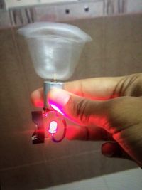
| + | It was weekend 2 already. Our assignment for that weekend was to make a toy. No instructions, details, nothing! Just make a toy. I was extremely anxious about this assignment. After a lot of brainstorming, I thought of making a very basic toy using a motor and battery and an LED. A mixer for kids’ kitchen sets. | ||
| + | |||
| + | |||
| + | |||
| + | |||
| + | |||
| + | |||
| + | |||
| + | |||
| + | |||
| + | |||
| + | |||
| + | |||
| + | |||
| + | |||
| + | |||
| + | |||
| + | |||
| + | |||
| + | |||
| + | |||
| + | |||
| + | |||
| + | |||
| + | '''555 Oscillator''' | ||
| + | |||
| + | [[File:IMG_3930.jpg|200px|thumb|right|555 Oscillator]] | ||
| + | |||
| + | |||
| + | When I first laid eyes on a 555, I was super intrigued by the shape and size of it. That's the thing about most electronic components; they're so tiny in size, yet they carry out major functions so efficiently. With a 555, and an easy but intricate circuit, including a potentiometer, LDR, I managed to produce effectively varying sounds. | ||
| + | |||
| + | |||
| + | |||
| + | |||
| + | |||
| + | |||
| + | |||
| + | |||
| + | |||
| + | |||
| + | |||
| + | '''LM386''' | ||
| + | |||
| + | [[File:IMG_4266.jpg|200px|thumb|right|LM386 IC with a Pot, capacitors, resistor, audio jack and speaker]] | ||
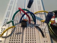
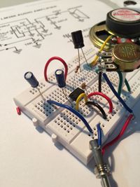
| + | |||
| + | LM386 is an IC which is an Integrated Circuit. I made use of this IC to build an Audio Amplifier with a male 3.5mm jack connected to it. Building this circuit was another one of those really fascinating sessions. By this point of the class, we were almost half way through to the end of class and I was beginning to understand electronics as a subject and building a deeper interest in every single component that was being taught to us. One of the main reasons is that each and everything we did was completely new to me and it hugely increased my liking for electronics. Especially, when you have finally learned to read and understand a circuit and build it all by yourself and it turns out right. Thats when I realised how fulfilling and inspiring electronics can be. When the circuit was built, I tried connecting my phone through the audio jack but nothing happened. The speaker didn't respond. I got tense, but it only turned out that the jack didn't fit my phone properly. It worked perfectly fine on the phone of another. Nevertheless, that day left me feeling satisfied about the work I’d done and accomplished. | ||
| + | |||
| + | |||
| + | |||
| + | |||
| + | |||
| + | |||
| + | |||
| + | |||
| + | |||
| + | |||
| + | |||
| + | |||
| + | |||
| + | '''Amplifier''' | ||
| + | |||
| + | [[File:186376A2-CDB7-4311-9B6B-4DA66D4C631D-export.jpg|200px|thumb|left|My first experience with connecting a circuit on a PCB]] [[File:IMG_4629.png|200px|thumb|right|Succesful amplifier connected to the laptop and playing music+The circuit diagram for building an amplifier]] | ||
| + | |||
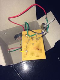
| + | This was one of my favourite assignments of all. My first experience with connecting a circuit on a PCB (Printed Circuit Board). This was my opportunity to finally put my soldering skills to test. I was super pumped up to make an amplifier. It took me about six hours to work on it, but when I finally was finished with it, it was a reward, truly! I still couldn't believe how far I’d gotten with this course. It was only a few days ago that I was facing trouble understanding series and parallel resistance and to only look at where I had gotten now, it is astonishingly satisfying. Building amplifiers and all! | ||
| + | |||
| + | |||
| + | |||
| + | |||
| + | |||
| + | |||
| + | |||
| + | |||
| + | |||
| + | |||
| + | |||
| + | |||
| + | |||
| + | |||
| + | |||
| + | |||
| + | |||
| + | |||
| + | |||
| + | |||
| + | |||
| + | '''Arduino Uno Basic''' | ||
| + | |||
| + | [[File:IMG_4286.jpg|200px|thumb|left|Making an LED blink]] [[File:IMG_4633.jpg|200px|thumb|right|Arduino Uno+LED+Pot]] | ||
| + | [[File:IMG_4631.jpg|200px|thumb|left|Manipulating the LED with shadow on the LDR]] | ||
| + | [[File:IMG_4632.jpg|200px|thumb|right|Manipulating the LED with light on the LDR]] | ||
| + | [[File:LDR+LED+Motor.png|200px|thumb|left|Code for LDR+LED+Motor]] | ||
| + | |||
| + | I was extremely excited about buying an arduino and using one. It was only a month before I took this course up that I was discussing with a friend of mine who is very much inclined towards electronics as a subject and hobby. Even when I’d signed up for this course, I had no clue that we’d be learning to create with Arduinos. When we were asked to buy one, it completely took me by surprise, but for the better. I had always wanted to learn how to use a mini computer. This course is by far one of the most productive courses I have taken up. It may not have been my first preference, but I most definitely do not regret it one bit. Step by step, we started learning how to code using a software we downloaded before our first class on Arduino. I started with learning how to make an LED blink. I then learned how to adjust the intensity of the current flow to the LED through a potentiometer and also how to manipulate the LED using an LDR. With each progressing day of this course, I got to learn more and more. That’s the best feature! | ||
| + | |||
| + | |||
| + | |||
| + | |||
| + | |||
| + | |||
| + | |||
| + | |||
| + | |||
| + | |||
| + | |||
| + | |||
| + | |||
| + | |||
| + | |||
| + | |||
| + | |||
| + | |||
| + | |||
| + | |||
| + | |||
| + | |||
| + | |||
| + | |||
| + | |||
| + | |||
| + | |||
| + | |||
| + | |||
| + | |||
| + | |||
| + | |||
| + | |||
| + | |||
| + | |||
| + | |||
| + | |||
| + | |||
| + | |||
| + | |||
| + | '''Knight Rider''' | ||
| + | |||
| + | [[File:IMG_4634.jpg|200px|thumb|left|Knight Rider]] [[File:Knight Rider.png|200px|thumb|right|Knight Rider Code for Arduino]] | ||
| + | |||
| + | This exercise is inspired by Knight Rider, an American science fiction show. The highlights were that it featured an artificially intelligent car which was used to fight crimes. The car was virtually indestructable. A few years earlier, growing up, I had watched a little bit of the show and I remember being completely mesmerised by the car. When our facilitator, Yashas, played a video of Knight Rider on YouTube, immediately I had flashbacks from way back and a lot of reminiscent memories attached to those flashbacks. This course has given more times with an adrenaline rush and excitement to work than it’s not. I’ve had my fair share of downs, but the great experiences and learnings weigh more. Back to the Knight Rider, the front grill of the car had an array of LEDs which would light up in a sequence and back and forth, which is actually called an Anamorphic Equaliser. I would some day like to own a car like that. Or after this class, maybe I could do it myself? | ||
| + | |||
| + | |||
| + | |||
| + | |||
| + | |||
| + | '''We're Magicians''' | ||
| + | |||
| + | [[File:IMG_4371.jpg|200px|thumb|left|]] [[File:IMG_4364.jpg|200px|thumb|right]] | ||
| + | [[File:IMG_4372.jpg|200px|thumb|left]] [[File:IMG_4381.jpg|200px|thumb|right]] | ||
| + | [[File:IMG_4379.jpg|200px|thumb|right|Voila!]] | ||
| + | |||
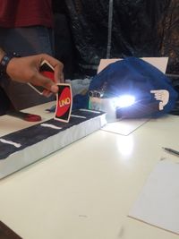
| + | For this weekend project, we worked in a group of three. Rajat, Shravan and I spent hours brainstorming ideas for what is supposed to be a magic instrument. Since this is a class on sensors, we were thinking on those line, as to what illusion can we create for our audience. Our initial idea was to make a car that runs on light. Basically, using an LDR which would be connected to two DC motors that would run the wheels of the car. For hours we tried to figure out how to work the motor out but since 9V batteries are not enough power supply for DC motors, we tried using a transistor. We looked high and low on the internet for a circuit that would match our requirement, but we failed to find any. We then got ambitious and thought of making use of a servo motor. That idea failed too. In the last minute, we decided to make use of an ultrasonic sensor. The main function of an ultrasonic sensor is that it converts ultrasound waves to electrical signals. It senses the distance of any given object. Based on this theory, we used the Arduino Uno and ran a code which included sending electrical signals for different functions according to the distance of an object from the sensor. We soldered five LEDs in a circuit to a PCB and designed a game such that we had five varying distances marked from the sensor. Each marked point had the function of a given number of LEDs lighting up. We chose to use playing card numbers from 1-5 as our props for the magic show. You let someone from the audience pick a card and not show you (but you really know which card he/she has picked up, since you know how you lined the cards up). If the card is number 3, place it in slot number 3 and immediately our Mr. Magic will pick up on it and light up three LEDs for the audience. Magical, isn't it? | ||
Latest revision as of 02:45, 18 October 2015
My First Robot
Day 1 of Sensors, Probes and Detectors. I was extremely excited. My facilitator, Yashas, only tells us all that we were going to build a robot. And I was a little nervous. I had absolutely no prior know-abouts regarding Electronics, except in school though. What I had studied in school was already hazy and I couldn’t contain my excitement, on day one of this class, in anticipation of learning an entirely new subject. This was my first experience with learning how to solder. Truth be told, mine was the worst kind of soldering in the class. Although, eventually, I got the hang of it and now, I absolutely enjoy using the solder iron. We were only given instructions as to the making of a robot. Honestly, I didn't understand much about what I was doing, but I was only following the instructions. I was the last to finish making my robot, but it was not at all in vain. I took time to understand the logic behind why we did what we did. That was a fulfilling day, alright.
Lemon Battery
This was our first weekend and it was time for our first weekend homework. When I heard that we were to make a battery out of lemons and light up a LED, I was excited as well as tense as to how I was going to make a lemon battery in the first week itself, without any instructions or any knowledge about Electronics. I resorted to YouTube and found that all it took was a big, raw lemon, a copper wire and a nail. I only thought that it was that easy. When I actually tried it, I faced a lot of trouble acquiring enough voltage to light up the LED. When, finally, in class four of us combined our lemon batteries, we finally got very little voltage enough to let the LED glow very dim.
Switch
I particularly enjoyed the rate at which the class progressed. Many have complained that it was all going too slow. But on the other hand, I liked the systematic way of teaching in the class. One component per day. Understood well. Especially, for someone like me who needed time to get acquainted with the rules and everything else within the world of electronics. The first component we learnt of was a switch. We all know that a switch, technically, is something that helps us complete any circuit. Now keeping this in mind, we had to make our own switch. We made two types of switches. One, where an LED would light up with pressure put on one loose end of the circuit to sit onto the other end. Basically, we attached this circuit to a slipper, wherein when there is pressure put down by the foot, the LED lights up. The second kind of switch we made was for a book. When the book was opened, the two loose ends of the circuit would meet and thereby, complete the circuit, resulting in the LED lighting up.
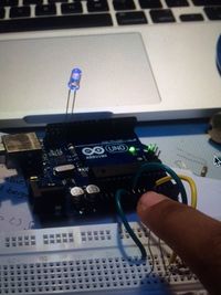
Breadboard and LEDs
Next, we learned how to use and work on a breadboard. I had never seen a breadboard before, let alone working with one. It took me quite a while to understand how to build circuits on the breadboard. Today, I think breadboards are awesome! I used to see a lot of my classmates work in class like they knew exactly what they were doing and that they already understood what had been explained. I felt out of place for a few days in the beginning because I thought I was the only one who didn't understand too soon. Slowly, I began to cope and my levels of interest rose. The most basic thing to use as an element to understand anything is an LED. Here too, we started with making a very simple circuit by just lighting up an LED. We had to use the 9V batteries for the circuit. Since LEDs cannot sustain 9V, we had to make use of a resistor. When we were good with making the circuit for one LED lighting up we made one with two or three or four LEDs. The basic principle is that an LED has two legs; one longer than the other. The longer leg is connected to ground whereas the shorter leg goes to the positive source.
Potentiometer
Along with the lighting of the LEDs, we made use of a new component called a ‘Potentiometer’. I was extremely fascinated by the fact that it is a potentiometer used in music systems to increase or reduce the volume. The potentiometer adjusts the resistance in the circuit and this is what helps in the high/low output.
Multimeter
A multimeter, I learnt, is a measuring device used to measure different kinds of units, which includes Ohms (for measuring the resistance an object has tooffer), Voltage and electric current. These vary over ranging values and are effective in almost every stage of working with electronics. Normally, there are meters to measure only a particular unit. For example, an Ohmmeter, a Voltmeter, etc. A multimeter is portably convenient as well as does the trick for most jobs.
Capacitor
A capacitor is an extremely useful component. Although, the ones we have used in class were a little lower in capacitating power, I realise that they are very useful in cases where one doesn't need to connect to a power source. The capacitor stores some amount of energy which can be made use of. It is like a power backup.
Diode
I must’ve studied of a diode in school, but the memory of that learning had completely washed off. The word ‘diode’ sounded familiar, but I had completely forgotten about its function and use. Understanding that a diode marks the flow of current in only one direction is a refreshing experience. I have received so much joy in understanding the littlest of components of electronics.To someone well-acquainted with electronics this kind of excitement may seem unnecessary. But greater joy comes to me when I understand the 1+2+1+3 and not just 7 as a whole.
Transistor
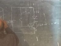
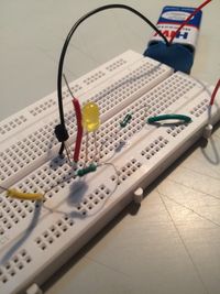
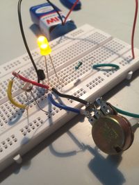
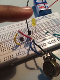
To an electronics guy, a transistor was a legendary innovation. I hadn't known the importance of a transistor up until I heard it through Mr. Bala in this class. Uptil until this far, we were only used to working with components that had two legs. Even though the potentiometer has three legs, we made use of only two. A transistor is an amplifier, said Mr. Bala. It amplifiers any given input and gives an output much larger than what it receives. This is known as gain. I tried many variations to a circuit with a transistor. First, I built a circuit with a human switch, wherein, one or two humans can close the circuit by touching the two open ends of the wires jutting out of the circuit. Then, I built a circuit with an LDR and a 10K Potentiometer, wherein, the resistance could be adjusted, as well as, the LDR's reaction to light would affect the LED's performance. That day was very productive, fast-paced and enlightening day. Literally!
LDR
An LDR is a Light Dependent Resistor. It has a photosensitive surface which reacts to light. So in a circuit with an LED, when the photosensitive surface of the LDR comes in contact with light, the LED goes on immediately. When the source flight is cut off or the LDR is surrounded by darkness, the LED goes off. We also made use of a speaker, in place of/along with the LED in the circuit. Similar to the LED, the speaker also gave sound output with the LDR coming in and out of contact with light. The part where the speaker exercise happened, the entire class went crazy with excitement. Different people had different types of sound output from their speakers. It was interesting to hear all the weird eery sounds the speakers were collaboratively making and most of all, for the first time, a noisy class is was what was expected by everyone, including our facilitators.
Toy
It was weekend 2 already. Our assignment for that weekend was to make a toy. No instructions, details, nothing! Just make a toy. I was extremely anxious about this assignment. After a lot of brainstorming, I thought of making a very basic toy using a motor and battery and an LED. A mixer for kids’ kitchen sets.
555 Oscillator
When I first laid eyes on a 555, I was super intrigued by the shape and size of it. That's the thing about most electronic components; they're so tiny in size, yet they carry out major functions so efficiently. With a 555, and an easy but intricate circuit, including a potentiometer, LDR, I managed to produce effectively varying sounds.
LM386
LM386 is an IC which is an Integrated Circuit. I made use of this IC to build an Audio Amplifier with a male 3.5mm jack connected to it. Building this circuit was another one of those really fascinating sessions. By this point of the class, we were almost half way through to the end of class and I was beginning to understand electronics as a subject and building a deeper interest in every single component that was being taught to us. One of the main reasons is that each and everything we did was completely new to me and it hugely increased my liking for electronics. Especially, when you have finally learned to read and understand a circuit and build it all by yourself and it turns out right. Thats when I realised how fulfilling and inspiring electronics can be. When the circuit was built, I tried connecting my phone through the audio jack but nothing happened. The speaker didn't respond. I got tense, but it only turned out that the jack didn't fit my phone properly. It worked perfectly fine on the phone of another. Nevertheless, that day left me feeling satisfied about the work I’d done and accomplished.
Amplifier
This was one of my favourite assignments of all. My first experience with connecting a circuit on a PCB (Printed Circuit Board). This was my opportunity to finally put my soldering skills to test. I was super pumped up to make an amplifier. It took me about six hours to work on it, but when I finally was finished with it, it was a reward, truly! I still couldn't believe how far I’d gotten with this course. It was only a few days ago that I was facing trouble understanding series and parallel resistance and to only look at where I had gotten now, it is astonishingly satisfying. Building amplifiers and all!
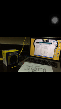
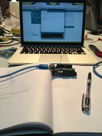
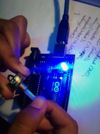
Arduino Uno Basic
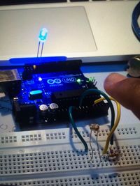
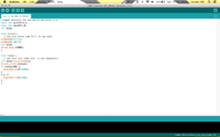
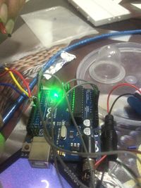
I was extremely excited about buying an arduino and using one. It was only a month before I took this course up that I was discussing with a friend of mine who is very much inclined towards electronics as a subject and hobby. Even when I’d signed up for this course, I had no clue that we’d be learning to create with Arduinos. When we were asked to buy one, it completely took me by surprise, but for the better. I had always wanted to learn how to use a mini computer. This course is by far one of the most productive courses I have taken up. It may not have been my first preference, but I most definitely do not regret it one bit. Step by step, we started learning how to code using a software we downloaded before our first class on Arduino. I started with learning how to make an LED blink. I then learned how to adjust the intensity of the current flow to the LED through a potentiometer and also how to manipulate the LED using an LDR. With each progressing day of this course, I got to learn more and more. That’s the best feature!
Knight Rider
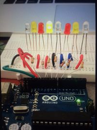
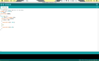
This exercise is inspired by Knight Rider, an American science fiction show. The highlights were that it featured an artificially intelligent car which was used to fight crimes. The car was virtually indestructable. A few years earlier, growing up, I had watched a little bit of the show and I remember being completely mesmerised by the car. When our facilitator, Yashas, played a video of Knight Rider on YouTube, immediately I had flashbacks from way back and a lot of reminiscent memories attached to those flashbacks. This course has given more times with an adrenaline rush and excitement to work than it’s not. I’ve had my fair share of downs, but the great experiences and learnings weigh more. Back to the Knight Rider, the front grill of the car had an array of LEDs which would light up in a sequence and back and forth, which is actually called an Anamorphic Equaliser. I would some day like to own a car like that. Or after this class, maybe I could do it myself?
We're Magicians
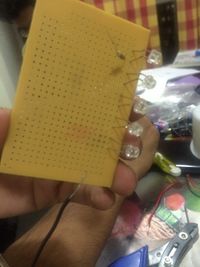
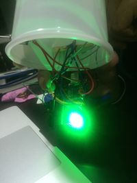
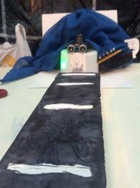
For this weekend project, we worked in a group of three. Rajat, Shravan and I spent hours brainstorming ideas for what is supposed to be a magic instrument. Since this is a class on sensors, we were thinking on those line, as to what illusion can we create for our audience. Our initial idea was to make a car that runs on light. Basically, using an LDR which would be connected to two DC motors that would run the wheels of the car. For hours we tried to figure out how to work the motor out but since 9V batteries are not enough power supply for DC motors, we tried using a transistor. We looked high and low on the internet for a circuit that would match our requirement, but we failed to find any. We then got ambitious and thought of making use of a servo motor. That idea failed too. In the last minute, we decided to make use of an ultrasonic sensor. The main function of an ultrasonic sensor is that it converts ultrasound waves to electrical signals. It senses the distance of any given object. Based on this theory, we used the Arduino Uno and ran a code which included sending electrical signals for different functions according to the distance of an object from the sensor. We soldered five LEDs in a circuit to a PCB and designed a game such that we had five varying distances marked from the sensor. Each marked point had the function of a given number of LEDs lighting up. We chose to use playing card numbers from 1-5 as our props for the magic show. You let someone from the audience pick a card and not show you (but you really know which card he/she has picked up, since you know how you lined the cards up). If the card is number 3, place it in slot number 3 and immediately our Mr. Magic will pick up on it and light up three LEDs for the audience. Magical, isn't it?
