Difference between revisions of "Pranav viswanath"
(→Step 4 - Using transistor to power servo) |
(→Challenges) |
||
| (37 intermediate revisions by one user not shown) | |||
| Line 173: | Line 173: | ||
== Process == | == Process == | ||
| − | === Step 1 - Miniservo control using IR sensor === | + | I went through a lot to get this to work.. so I have documented my process in 10 steps. |
| + | === Step 1 - Miniservo control using IR sensor === | ||
| + | The most crucial joint required to do a push up is the elbow joint. Without that joint doing a Push up is impossible. To mimic that hand movement, using a Servo motor was my best option. I was very skeptical about how much weight it can lift but I just wanted to first get it to work. | ||
| + | [[File:step 1.jpg]] | ||
| + | |||
=== Step 2 - LCD display to count number of reps=== | === Step 2 - LCD display to count number of reps=== | ||
| − | === Step | + | With the servo motor working fine, my next step was to figure out how to use an LCD screen to display the number of Reps. I have used the example program to check whether the LCD is working. I didn't that Iam supposed to use a potentiometer to adjust the brightness of the screen for it display anything on the screen. I did not know this and i thought my LCD wasn't working. Thanks to sushil i know how to use an LCD <br> |
| − | === Step 4 - Using TIR 122 transistor to power servo === | + | [[File:step 2.1.1.jpg]] [[File:step 2.2.jpg]] |
| + | |||
| + | === Step 4 - Mechanism === | ||
| + | 1. JOINT <br> | ||
| + | The mechanism is very important to my project. it is going to stitch everything together. i didn't know how to make a pivot joint. i had an old mechanix set lying around in my pg. I just used that because it already had holes and even though i wasn't sure how to use it, it just felt right to start with that. I attached two hands of the mechanix set using a bolt and nut and i deliberately did not tighten the nut completely.. i wanted the hands to move freely. <br> | ||
| + | 2. FIXING SERVO <br> | ||
| + | I also had to fix the servo motors on a surface otherwise the servo started rotating instead of its gear. <br> | ||
| + | |||
| + | 3. SERVO MOVEMENT <br> | ||
| + | I spent hours together on something very silly. I used the sweep program to make it go from 0 to 90 and then again 90 to 0. The problem was that both servos moved in the same direction. I wanted to go clockwise and the other to go anticlockwise. I spent a lot of time on the for loop and tried various algorithms and nothing seemed to work. Then I Realized i can just flip it and make go anti clock wise. | ||
| + | |||
| + | |||
| + | |||
| + | [[File:4. mechanism.jpg]] | ||
| + | |||
| + | === Step 4 - Upgrade to Big Servo === | ||
| + | The mini blue color servos are not powerful enough to lift a life size human figure. I had to buy big servos. The problem with big servo is that it takes a lot of power and only one can be powered at a time from the arduino board. two motors can be plugged into the 5v pin but the servo motors will start malfunctioning and won't work properly. I couldn't power it directly using a 9v battery also. | ||
| + | |||
| + | === Step 5 - Using TIR 122 transistor to power servo === | ||
| + | My facilitator advised me to use a TIR transistor to power the servo externally using a 9v battery. It actually worked! but the only drawback was that I couldn't make it work along with a sensor. The servo started malfunctioning when I added the IR sensor to the circuit. Connecting the servo motor to TIR transistor confused me a little bit because i was able to find references only for DC motors. Taking that as reference, i used common sense to figure out the circuit. luckily my first attempt itself was a success which never happens. The servo motors work without sensors now <br> | ||
| + | |||
| + | [[File:step 5.1.jpg]] [[File:step 5.2.jpg]] <br> | ||
| + | |||
| + | {{#ev:youtube|R27lr3i4Yuk}} | ||
| + | |||
| + | === Step 6 - Motor shield === | ||
| + | |||
| + | I don't have a picture but I borrowed a motor shield from the lab and tried using it. I thought that the shield was the solution to all my problems but it was also able to power only one black servo motor at a time. | ||
| + | |||
| + | === Step 7 - Two separate arduino boards to power each servo === | ||
| + | Since one big servo works properly with Arduino, i thought i would connect two arduino boards powering each servo separately with the signal coming from one arduino. it worked but for some reason i was not able to include a sensor in the circuit. i don't know whether it was the lighting or the connections I wasn't even able to upload code on my arduino. I don't know where i went wrong. i completely lost it. i removed all the wires and tried uploading the code then it worked. By that time i had to return the second arduino that i had borrowed from the lab. I gave it a body made from wood. I wasn't satisfied with it though. | ||
| + | |||
| + | === Step 8 - Switching back to batteries to power servo externally === | ||
| + | I somehow wanted to make it work by using just one arduino board. i went online and searched for how to power servo externally without using transistors. someone had used 4 AA batteries inside a battery holder to directly power the servo. I tried that and it worked :') .. I added an IR sensor to the circuit and it still works. Finally it is working. | ||
| + | |||
| + | {{#ev:youtube|84cANhyJfvc}} | ||
| + | |||
| + | === Step 9 - bigger and better === | ||
| + | Now with the servo working properly along with the IR sensor, I wanted to make the whole thing bigger. I want to push the servo to its limit. Instead of a small prototype, Iam currently working on a life size model using PVC pipes. it is still work under progress<br> | ||
| + | |||
| + | [[File:9.JPG]] [[File:10.JPG]] [[File:13.JPG]] [[File:14.JPG]]<br> | ||
| + | |||
| + | [[File:12.JPG]] [[File:11 s.JPG]] | ||
| − | === Step | + | === Step 10 - Final output === |
| − | + | ||
| − | == Code == | + | == Code == |
| + | === Servo code === | ||
| + | [[File:push up code.png]] | ||
| − | == Challenges == | + | == Challenges == |
| + | 1. controlling two big servos with IR <br> | ||
| + | 2. building the structure <br> | ||
| + | 3. using pvc pipes to make a bigger model <br> | ||
| + | 4. wasn't able to spend enough time on prototyping and experimenting <br> | ||
| + | 5. Elbow joint<br> | ||
| + | 6. Not able to use IR sensor properly in daylight <br> | ||
| + | 7. Balancing the figure<br> | ||
| + | 8. powering one servo externally <br> | ||
| + | 9. insufficient materials <br> | ||
| + | 10. Making the whole setup portable | ||
| − | == Final Output == | + | == Final Output == |
| + | Will upload it once everything is done | ||
| − | == Overall Reflection == | + | == Overall Reflection/Take away == |
Latest revision as of 10:33, 12 April 2017
Contents
- 1 INTRODUCTION
- 2 BASICS
- 3 LAKE VISIT
- 4 PROJECTS
- 5 Activity
- 6 FINAL PROJECT
- 6.1 Concept Iteration
- 6.2 Process
- 6.2.1 Step 1 - Miniservo control using IR sensor
- 6.2.2 Step 2 - LCD display to count number of reps
- 6.2.3 Step 4 - Mechanism
- 6.2.4 Step 4 - Upgrade to Big Servo
- 6.2.5 Step 5 - Using TIR 122 transistor to power servo
- 6.2.6 Step 6 - Motor shield
- 6.2.7 Step 7 - Two separate arduino boards to power each servo
- 6.2.8 Step 8 - Switching back to batteries to power servo externally
- 6.2.9 Step 9 - bigger and better
- 6.2.10 Step 10 - Final output
- 6.3 Code
- 6.4 Challenges
- 6.5 Final Output
- 6.6 Overall Reflection/Take away
INTRODUCTION
I am Pranav Viswanath, a second year student majoring in Experimental Media Arts. I had opted for this course especially because sensors have always fascinated me. Although the process of working on programming is quite tedious and at times, frustrating, the output I get out of it has never failed to satisfy me. This has turned out to be the best way for me to express myself and communicate to the world because I have perennially been in love with electronics. I’m also interested in spirituality and philosophy. There is already too much hatred in this world and I really think I can integrate technology and spirituality to make this world a better place.
BASICS
What is a resistor?
All materials resist the flow of electric current at some level. A resistor is a device specifically meant for resisting the passage of an electric current.
Resistors in Series
Resistors connected in Series are chained together in a single line. Since all the current flowing through the first resistor has no other way to go it must also pass through the second resistor and the third and so on. Then, resistors in series have a Common Current flowing through them as the current that flows through one resistor must also flow through the others as it can only take one path. Then the amount of current that flows through a set of resistors in series will be the same at all points in a series resistor network
Resistors in parallel
In a parallel resistor network the circuit current can take more than one path as there are multiple paths for the current. Then parallel circuits are classed as current dividers. Since there are multiple paths for the supply current to flow through, the current may not be the same through all the branches in the parallel network. However, the voltage drop across all of the resistors in a parallel network is the same. Then, Resistors in Parallel have a Common Voltage across them and this is true for all parallel connected elements.
capacitors
capacitor works like a battery. it stores charge. While batteries and capacitors have similarities, there are several key differences. The potential energy in a capacitor is stored in an electric field, where a battery stores its potential energy in a chemical form. The technology for chemical storage currently yields greater energy densities than capacitors. However, when a battery is discharging it can be slower than a capacitor ability to
discharge because there is a latency associated with the chemical reaction to transfer the chemical energy into electrical energy. A capacitor is storing the electrical energy directly on the plates so discharging rate for capacitors are directly related to the conduction capabilities of the capacitors plates. A capacitor is able to discharge and charge faster than a battery because of this energy storage method also.
Personal reflection
I was really impressed when our facilitator took the effort to teach us the basics of electronics,circuits, ohm’s law, water bucket analogy even though this was supposed to be an advanced level class. I realized how rusty my memory was and how much I didn’t know. I was truly humbled after revising the basics.
LAKE VISIT
The lake visit really changed my perspective on sensors. I was able to look beyond electronics. There is so much around me that I was unaware of. My vision has literally expanded after observing microbes under a microscope. It is a whole new world. Maybe communicating with bacteria and small life forms is our first step towards becoming one with nature
PROJECTS
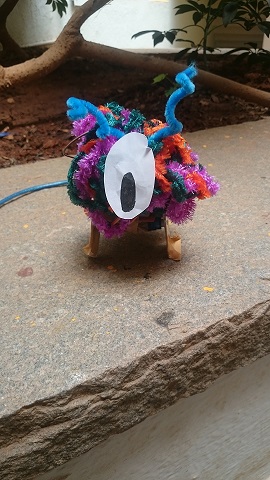
Touch me not monster
Process
Exploring Servo motor
We didn't know where to start. one of us had a servo motor lying around. we just wanted to understand how it works first.
Controlling two servos using IR sensor
We connected one more servo and at this point we had three ideas
1.pinball game
2.half zombie
3. creepy monster
we went ahead with the creepy monster because servo motor control wasn't smooth enough to make a pinball game or a zombie.
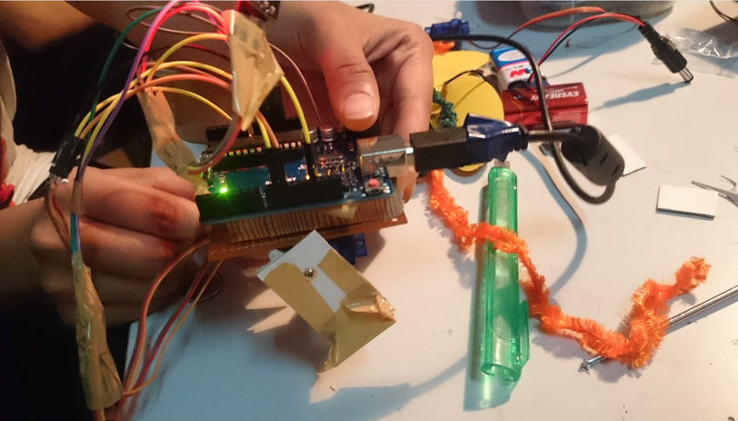
Building the Structure
Building the structure was the trickiest part. It just couldn't stand properly
Code
Connections
servo 1 :
signal to pin 9
voltage to 5v arduino
ground to arduino ground
servo 2 :
signal to pin 10
voltage to 9v battery +ve terminal
ground to arduino ground
9v -ve to arduino ground
IR sensor:
analog pin to A0
vcc to 5v arduino
ground to arduino ground
Output
youtube link :
challenges and Reflection
challenges
1. we were not able to predict in which direction the motor will move
2. did not really understand the code
3. had problems making it stand
4. did not work under direct sunlight
5. limited time
Honestly speaking, we did not plan to do this. we just ended up with a cute fluffy creature. working in a group was a great opportunity to bond as a team.
Pulse sensor
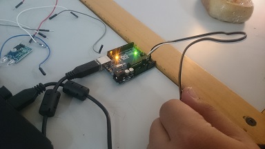
Using the pulse sensor was actually a cake walk . The connections were simple and like any other sensor with 3 pins.
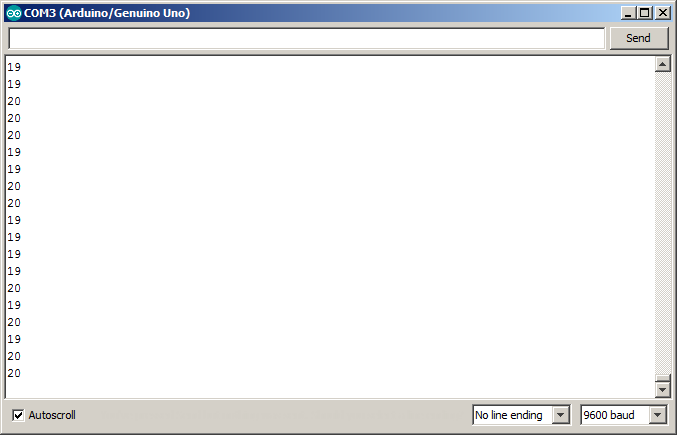
Readings
code
Turbidity Sensor
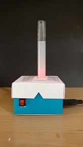
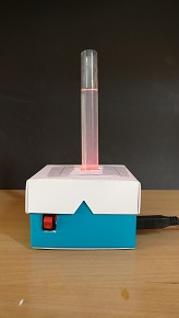
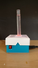
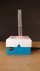
Process
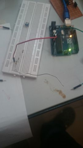
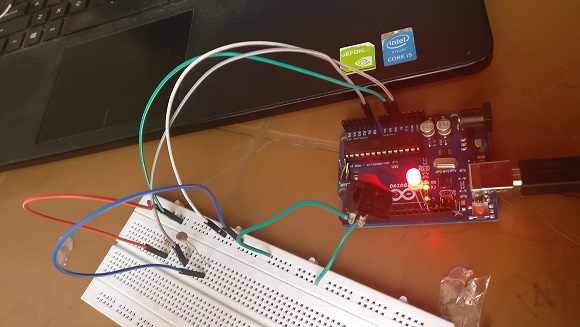
LDR cicuit with switch
My first thought was " How am I going to build a sensor? " but after I checked the turbidity sensor that was already there in the lab, I understood how it works. I learnt an important lesson today.No matter how complex something is, it can be broken down and analysed. It is not that scary anymore.You don't have to super intelligent to achieve something.All it takes is just patience and peseverance. Programming is just like venturing into the sea. you will have to go against the tide initially and it is going to be difficult. As you keep moving forward the sea becomes calmer and after a point it becomes completely calm. So just because you had to cross the tides in the beginning, don't think that you are required to do it all the way. It gets easier.
Putting it all together
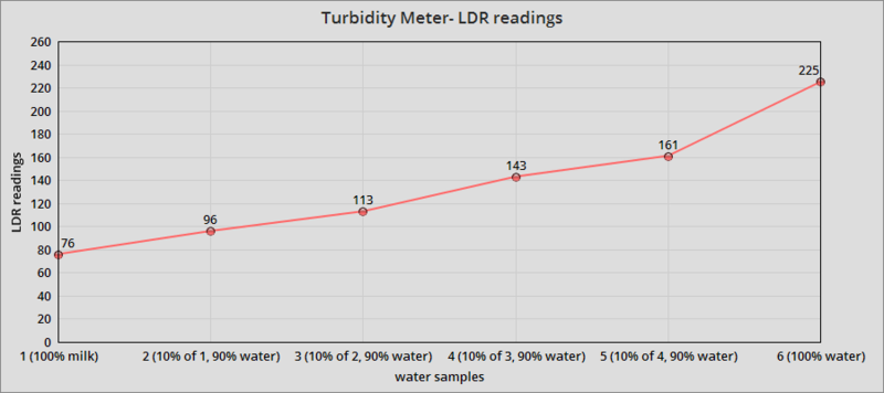
Taking the readings
Graph
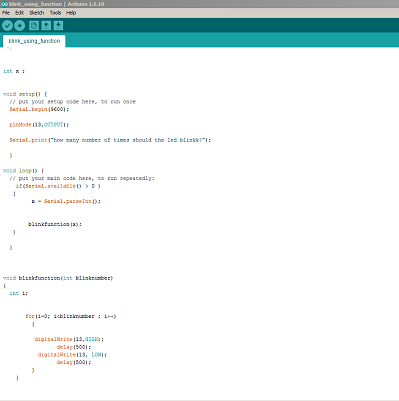
LED blink using fuction and communicating with serial moniter
I will never forget this program because i have explained it so many times to my friends. Each time I explained, I covered every line including the absolute basics like why we use a semi colon at the end of each statement. I gained so much more clarity and i reached a point where i could i type the program with my eyes closed. I did not memorize it though.. i just understood it with great clarity. I got so used to discussing my thoughts with people that i actually felt more comfortable and confident while working with someone on a program. I worked better when I had to explain what i was doing as it gave me more clarity. The questions my peers asked while learning taught me a lot of things as well. I wouldn't have thought of those questions.
Code
Challenges
Making the LED blink using a function wasn't really that difficult, i took a lot of time to figure out how to take input from the serial monitor. I kept using the function " serial.Read() " and it did not work. It took me a long time to figure out that Serial.Read() calculates the size of the number(calculates how many bytes of memory is required) instead of actually taking the data. while explaining this to one of my peers I came up with an analogy. This is how I explained the program.
what are functions ?
Functions are people who can be hired to do a specific job in your program. just like how pinMode() tells the arduino which pin you are going to use and the state of the pin, there are a lot of predefined functions in the Arduino library. people didn't understand when i told them it reads the number of bytes. So I gave them an analogy which they can relate. suppose you want to play an mp3 song, this Serial.Read() function will calculate the file size of the song, length of the song etc.. but you want it to play the song. so you use a different function called Parseint().
Parseint() takes the number as such in integer format.. it is specifically meant for giving input to the serial monitor.
LED level control using Potentiometer
Challenges
Understanding how array works was overwhelming and confusing.
I was able to get it to light up one after the other by calibrating the potentiometer but I had to sacrifice my lunch break to make it turn it off one by one. I just had to tweak the for loop a little bit but I figured out how to do that only after a lot of trial and error. After making so many mistakes I'm now very comfortable with for loop and I know how it works.
EMF sensor
literally speaking, when we were asked to build an EMF sensor it was like asking to navigate our way out of a complex maze blind folded. After researching on the net we realized we just needed a conductor and plug it into one of the analog pins.
Activity
Futuristic human with extended senses
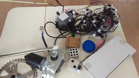
we(janvi and I) started out by collecting scrap that we could find in the campus
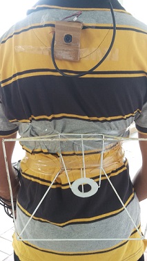
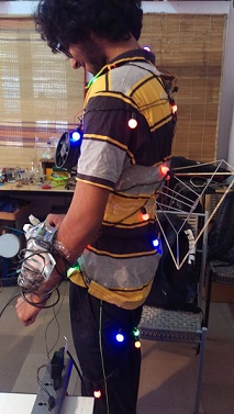
There is a webcam on my back for 360 degree vision.
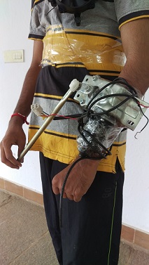
There is a jet back below the cam which can be controlled by the lever on my hand. the lever can also be used to excrete my waste while flying.
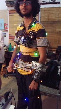
There is a fan on my chest which will help me take in more oxygen and give me super human strength
Those multicolored bulbs are psychedelic lights which can make people high just by looking at me
The whole experience was actually a makeshift super hero dream come true. I had a lot of fun going full retard and letting my imagination go wild.
FINAL PROJECT
Concept Iteration
Initially I wanted to make a Robot dog that resembles my dog since I miss my dog a lot. I just wanted to make a realistic dog so I wanted it to perform image tracking and face recognition to recognize the owner and follow them. After getting feedback I understood that it was my concept was too ambitious and I wanted to go for something simpler. Then I thought I would make a remote controlled dog that can fetch stuff from your room. I even wanted to give a scissor life and power it using a stepper motor so that it can reach things that are kept even on tables.
One other Idea I had was a life size work out companion that actually exercises along with you. My second Idea felt more original because there are only apps to support and I don't think anyone has ever made a workout companion robot but a lot of robot dogs are already there on the market.
After I made up my mind that I'm going to make a workout companion, I chose an exercise that can done any where and an exercise which is very convenient for balancing the robot. I chose the push up. Any other exercise would require the robot to execute complex movements and balance is one major criteria that I was concerned about.
Process
I went through a lot to get this to work.. so I have documented my process in 10 steps.
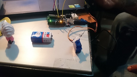
Step 1 - Miniservo control using IR sensor
The most crucial joint required to do a push up is the elbow joint. Without that joint doing a Push up is impossible. To mimic that hand movement, using a Servo motor was my best option. I was very skeptical about how much weight it can lift but I just wanted to first get it to work.
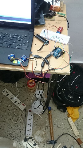
Step 2 - LCD display to count number of reps
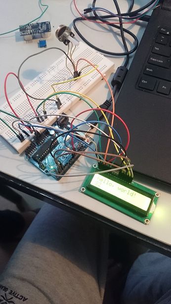
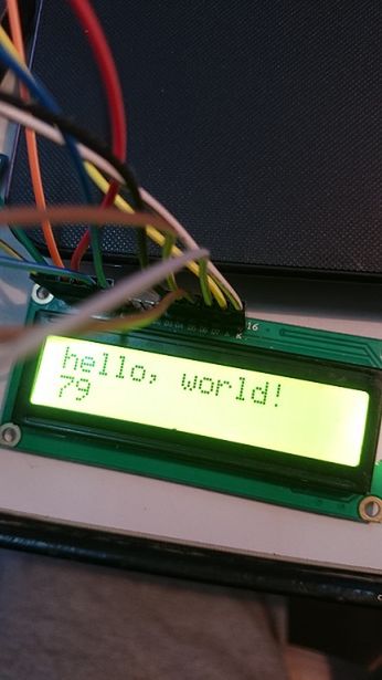
With the servo motor working fine, my next step was to figure out how to use an LCD screen to display the number of Reps. I have used the example program to check whether the LCD is working. I didn't that Iam supposed to use a potentiometer to adjust the brightness of the screen for it display anything on the screen. I did not know this and i thought my LCD wasn't working. Thanks to sushil i know how to use an LCD
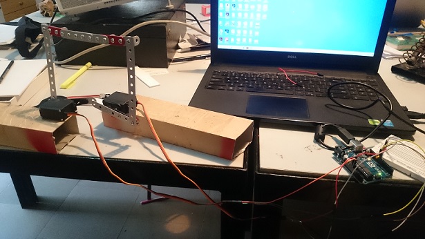
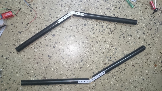
Step 4 - Mechanism
1. JOINT
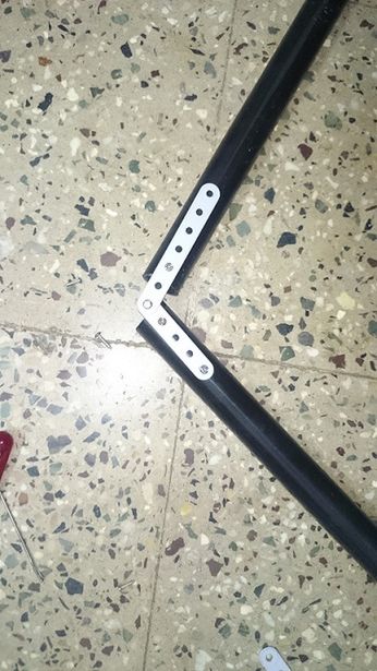
The mechanism is very important to my project. it is going to stitch everything together. i didn't know how to make a pivot joint. i had an old mechanix set lying around in my pg. I just used that because it already had holes and even though i wasn't sure how to use it, it just felt right to start with that. I attached two hands of the mechanix set using a bolt and nut and i deliberately did not tighten the nut completely.. i wanted the hands to move freely.
2. FIXING SERVO
I also had to fix the servo motors on a surface otherwise the servo started rotating instead of its gear.
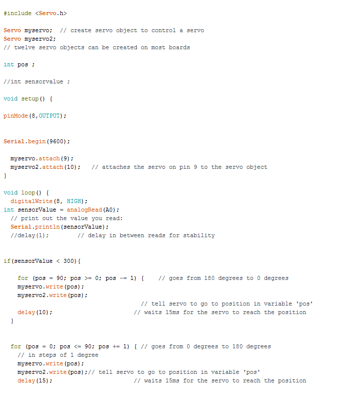
3. SERVO MOVEMENT
I spent hours together on something very silly. I used the sweep program to make it go from 0 to 90 and then again 90 to 0. The problem was that both servos moved in the same direction. I wanted to go clockwise and the other to go anticlockwise. I spent a lot of time on the for loop and tried various algorithms and nothing seemed to work. Then I Realized i can just flip it and make go anti clock wise.
Step 4 - Upgrade to Big Servo
The mini blue color servos are not powerful enough to lift a life size human figure. I had to buy big servos. The problem with big servo is that it takes a lot of power and only one can be powered at a time from the arduino board. two motors can be plugged into the 5v pin but the servo motors will start malfunctioning and won't work properly. I couldn't power it directly using a 9v battery also.
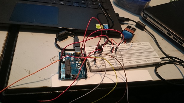
Step 5 - Using TIR 122 transistor to power servo
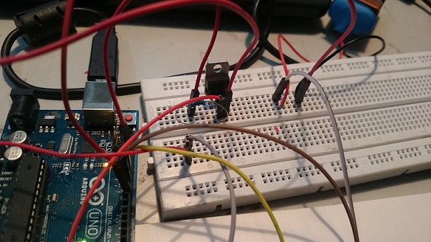
My facilitator advised me to use a TIR transistor to power the servo externally using a 9v battery. It actually worked! but the only drawback was that I couldn't make it work along with a sensor. The servo started malfunctioning when I added the IR sensor to the circuit. Connecting the servo motor to TIR transistor confused me a little bit because i was able to find references only for DC motors. Taking that as reference, i used common sense to figure out the circuit. luckily my first attempt itself was a success which never happens. The servo motors work without sensors now
Step 6 - Motor shield
I don't have a picture but I borrowed a motor shield from the lab and tried using it. I thought that the shield was the solution to all my problems but it was also able to power only one black servo motor at a time.
Step 7 - Two separate arduino boards to power each servo
Since one big servo works properly with Arduino, i thought i would connect two arduino boards powering each servo separately with the signal coming from one arduino. it worked but for some reason i was not able to include a sensor in the circuit. i don't know whether it was the lighting or the connections I wasn't even able to upload code on my arduino. I don't know where i went wrong. i completely lost it. i removed all the wires and tried uploading the code then it worked. By that time i had to return the second arduino that i had borrowed from the lab. I gave it a body made from wood. I wasn't satisfied with it though.
Step 8 - Switching back to batteries to power servo externally
I somehow wanted to make it work by using just one arduino board. i went online and searched for how to power servo externally without using transistors. someone had used 4 AA batteries inside a battery holder to directly power the servo. I tried that and it worked :') .. I added an IR sensor to the circuit and it still works. Finally it is working.
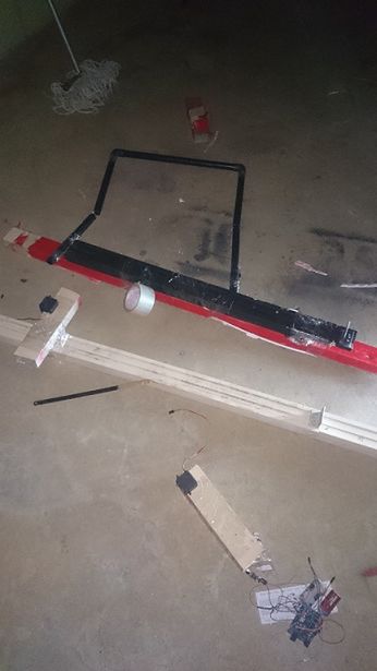
Step 9 - bigger and better
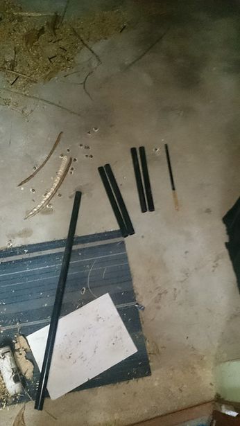
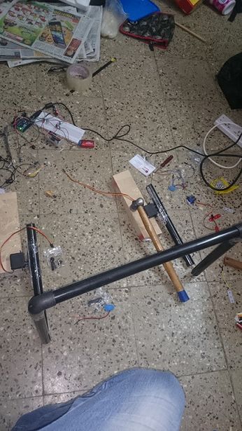
Now with the servo working properly along with the IR sensor, I wanted to make the whole thing bigger. I want to push the servo to its limit. Instead of a small prototype, Iam currently working on a life size model using PVC pipes. it is still work under progress
Step 10 - Final output
Code
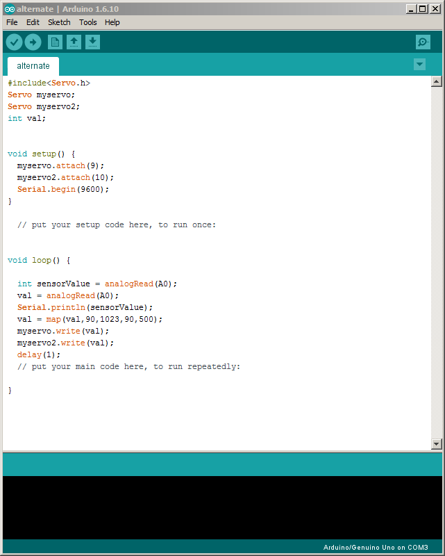
Servo code
Challenges
1. controlling two big servos with IR
2. building the structure
3. using pvc pipes to make a bigger model
4. wasn't able to spend enough time on prototyping and experimenting
5. Elbow joint
6. Not able to use IR sensor properly in daylight
7. Balancing the figure
8. powering one servo externally
9. insufficient materials
10. Making the whole setup portable
Final Output
Will upload it once everything is done
