Difference between revisions of "Dhruv"
| (2 intermediate revisions by one user not shown) | |||
| Line 109: | Line 109: | ||
This was probably the toughest yet most fun experiment for me. It was tough in the sense that I couldn't figure out the circuit diagram at all initially. But after quite some time of struggling, I got it. I understood the realistic diagram that was drawn on the road better than the actual circuit diagram, which I still can't understand. The sounds just got more weird by the end of the class and none of us wanted to pay attention to what was being taught next. It was a great experience. | This was probably the toughest yet most fun experiment for me. It was tough in the sense that I couldn't figure out the circuit diagram at all initially. But after quite some time of struggling, I got it. I understood the realistic diagram that was drawn on the road better than the actual circuit diagram, which I still can't understand. The sounds just got more weird by the end of the class and none of us wanted to pay attention to what was being taught next. It was a great experience. | ||
| + | |||
| + | Here are the clips demonstrating the 555 oscillator. | ||
| + | |||
| + | [https://youtu.be/ZWykR7djtWk] [https://youtu.be/KcsKNfXd2lA] [https://youtu.be/zF2xXVS-QSc] | ||
| + | |||
| + | ===Amplifier- LM386=== | ||
| + | |||
| + | When we started working on the breadboard model of this in class, I knew it wasn't going to be easy. I still had some difficulty following the 8-pin circuit diagrams so I was already somewhat behind, but I was still quite excited about building my own amplifier. So it took me some time, but eventually Phil Collins and Bono were received quite well. The sound quality was good and none of the connections were loose. I was quite happy by the end of it. The soldering part at home was a pain, though. I kept trying and failing. I tried soldering it so many times but I couldn't get it to work. It was really frustrating. Until finally I realized that I had a few connections wrong and therefore rectified it all and '''finally''' got it working. The box was fun to make. It turned out quite neat by the end of it I think. | ||
| + | |||
| + | [[File:Amp Dhruv 0.jpg |400px]] [[File:Amp Dhruv 1.jpg |400px]] | ||
| + | [[File:Amp Dhruv 2.jpg |400px]] [[File:Amp Dhruv 3.jpg |400px]] | ||
| + | |||
| + | ==Arduino== | ||
| + | |||
| + | Finally, the coding part. Earlier this year, I joined Code Academy and took up some tutorials on very basic HTML and CSS, which was basically to design the homepage of Airbnb. So that was all the HTML I knew. In the course description, when coding was mentioned, I didn’t think it would be about coding electrical components. So when we were asked to buy an Arduino, which I was told was something to code into, I thought it was a mini-computer of some sort. And when I got it, I saw that it was only a board. I was mildly disappointed. But when I did some research about the Arduino and all its possibilities, I was left in awe. There were so many projects that people had done and used it in so many creative ways, I was puzzled as to how I did not come to know of the Arduino before this course. | ||
| + | |||
| + | ===Blinking a LED=== | ||
| + | |||
| + | For the first assignment, when we were asked to blink a LED, I was quite excited. I already was getting the hang of the coding part. Since I was a little slower in class before, during the analog part of electronics, I thought I’d compensate by being a little ahead in the coding aspects at least. And that was finally happening. Blinking the LED was done quite easily and I was proud with myself. The commands were initially a little confusing but when they made sense to me, I found myself programming the commands I know with ease. | ||
| + | |||
| + | ===Knight Rider chasing lights=== | ||
| + | |||
| + | This was probably the coolest assignment. When we were shown the video at first, I thought it was a video played by mistake, because well, Knight Rider. But then as soon I saw the lights of the car, nostalgia struck and I was hoping that the assignment was what I was hoping it to be. And I was right. '''Yes.''' | ||
| + | We were asked to figure the coding out. And before using common sense, I went onto the internet and checked various websites for solutions to it. Then, later on, I realized what an idiot I’d been for doing that, as the solution was right there. I just had to do the same thing again and again and send the command backwards as well. As simple as that. Once I’d done that, I got the lights to chase each other but I was still quite unhappy with the stupidity I’d done. At the end of the class, we were asked to come up with a magic trick! '''What.''' | ||
| + | |||
| + | |||
| + | This is the video where I have demonstrated the Knight Rider light chase. | ||
| + | |||
| + | [https://youtu.be/ezeJ0y7wmCc] | ||
| + | |||
| + | |||
| + | LDR if and else video | ||
| + | |||
| + | [https://youtu.be/KaSO3ShB4eU] | ||
| + | |||
| + | |||
| + | LDR if and else with a capacitor video | ||
| + | |||
| + | [https://youtu.be/iaxlvMz_D_8] | ||
| + | |||
| + | Vibration motor video | ||
| + | |||
| + | [https://youtu.be/HP9s9IYlpfk] | ||
| + | |||
| + | ==Magic Box== | ||
| + | |||
| + | It was impossible to come up with something that could qualify as a magic trick. This was the time I was doing heave research on the internet as to the possibilities of the Arduino in terms of a magic trick. While going through that, I found so many other projects that I would love to continue in the future when I had the time. I found a project which was basically a magic wand, which would glow LED’s in letter formats, and by using long exposure shutter speeds, one can display sentences through it. I also found a lot of uses for the ultrasonic sensor. And a few more other projects. But I was still unclear with my idea for the magic trick. My partner and I brainstormed and then after what seemed like a million hours, I came up with the idea of making a box that would make something disappear. The idea was quite simple. It was to make a box with three layers. In the lowest layer, there would be the Arduino and the soldered PCB circuit. The layer above that would just be covered in cloth and on the top-most layer, there would be the object I would want to make disappear. The other components included a LDR and 360 degree servo motor. So when I place a black cloth on top, I would bring my hand closer to the LDR, thus triggering the servo motor attached to the platform to spin and rotate the platform with it, thus making the ball fall on top of the cloth in the lower layer. And as the motor would do a complete 360 degree spin, I would move my hand away, thus making the object disappear. It would’ve turned out to be a neat trick, had the motor not failed. As I was attaching the motor to the platform, glue went inside it, thus jamming the rotation. | ||
| + | |||
| + | This is the video showing the spinning of the platform for the Magic Box: | ||
| + | |||
| + | [https://youtu.be/QNPtJWtiBj0] | ||
Latest revision as of 10:07, 17 October 2015
Introduction
In school, I never really understood Physics, Chemistry or Electronics and so dropped them after class 10. But I was still fascinated by how electronics actually work. I thought circuits were extremely complex and complicated to understand which is why I never really delved deeper into the subject. But then after reading the course abstract and finding that there were no pre-requisites, I thought I could finally explore more into the subject of electronics as it will even be helpful in the future, no matter what field I choose. I feel that everyone must know basic amounts of electronics and circuitry, and especially us as artists and designers, as it broadens our knowledge and makes us more independent in our thinking approach without having to leave the technical stuff only to those who are already into it. And the extract also suggested a brief introduction to coding, which re-assured my decision of picking this course.
MicroRobots
Building our first robot
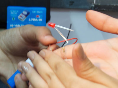
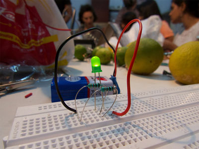
In every course, there's always the first-day excitement, curiosity and eagerness that's present in the classroom. So as I entered the class and saw all these components lying there, I was really keen on knowing how they worked and eager that by the end of the class, I hopefully would know how to operate at least a couple of these components. When we were told that by the end of the first class, we would make our very own robot, I was quite puzzled, as the word "robot" has some connotations synonymous with humanoids and Sci-Fi Hollywood movies. And there I was, getting excited after seeing one single LED light up as it came in contact with a 3v battery.
When we were shown the soldering iron, I was quite amazed at how it worked. I also thought Mr. Bala to be some sort of mad scientist when he told us all to touch the soldering iron to see if it was hot.
Trip to SP Road
When we were given the list of all the components, I half hoped the numbers next to each component would be its price. But alas, it was the quantity that we needed to buy. There went all my money.
The trip to SP Road was pretty exciting. Ganesh Chaturti was approaching and the streets were filled with Ganesh statues that were waiting to be immersed. They were spread all across Bangalore and so we encountered them all the way from Yelahanka to SP Road. In the car, we were discussing about how most of these components would not come in use and that after the course, we would take up our own projects and build from all the leftover components.
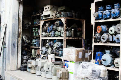
SP Road. Now when I even hear the name I can recall the whole place. It was nothing like I could have imagined. Before going, a few of my friends told me that it would be crowded with electronic shops and that it's a paradise of some sorts. Only when I saw the place with my own eyes did I understand what they meant.
When we went to Vishal Electronics, we realized that we had to withdraw money from an ATM. But when we asked around for the location of any nearby one, we were told that all of them are closed and that we need to go on the other side of the street to find it. We searched and searched for an hour and then finally found an Andhra Bank with an ATM in it.
On the way, we saw a lot of shops which had so much equipment. We were in so much awe. Never had we seen such a place before; a place bustling with people, shopkeepers selling the same products setting stalls right next to each other, etc. It was a lot to take in.
Vishal Electronics was crowded with people. We were the first ones to reach and thought that by the time we were done buying our components, he would run out of items. Then slowly more people from class started flooding in until the whole class was gathered there. It took a really long time for all the components to arrive. And since all of them were bought in bulk, we could negotiate and come to an agreement for a discount in the price.
Intro to Components
Battery
Mini Project: Making your own battery
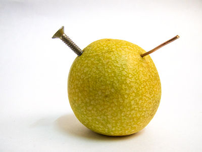
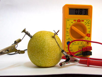
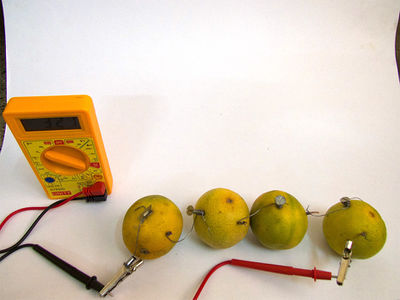
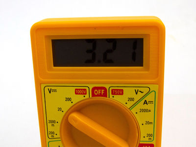
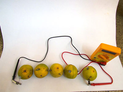
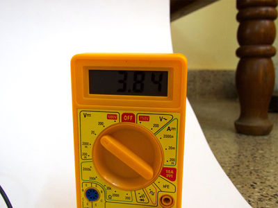
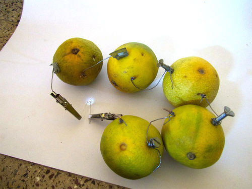
Making the lemon battery was an exciting project. When I was watching instructional videos on Youtube, I thought that once I learn to make this, I'd be able to power my laptop just with lemons. No, but in reality, I couldn't wait to get started with this. I realized, after searching around, that no shop in Yelahanka had copper wires, which were essential for the battery. So in the end, I found a shop where the man said he didn't have any copper, but I insisted he check his drawer and the shop and as he opened the drawer, I found some wire. It was very less, but it was something. And I managed with that. He was a little hesitant, but eventually he did give it to me. I also bought a multimeter from him.
At home, I started assembling my battery. I had copper wire, which I had to cut into pieces, just so I have enough. In the middle, I realized that I don't have enough nails, as I only bought 3, after all, the videos I watched had a requirement of only 3 nails. So I dug around the house and found some zinc sheet which my room-mate had used for his previous course. I cut out a bit of that and managed to make the battery successfully after a lot of tries.
Making your own switch
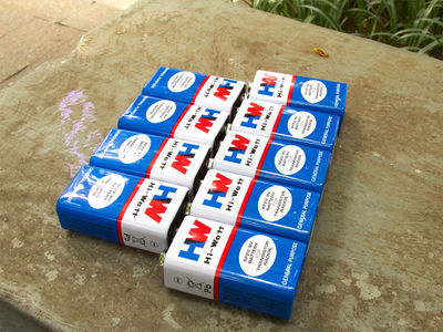
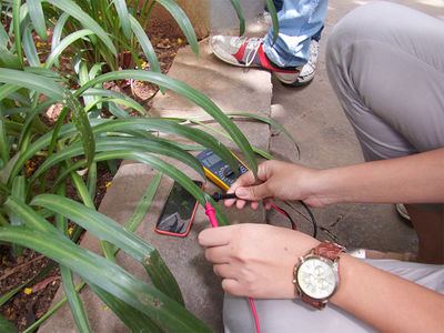
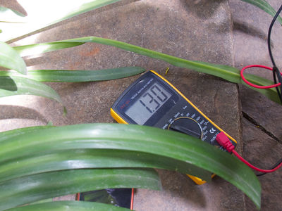
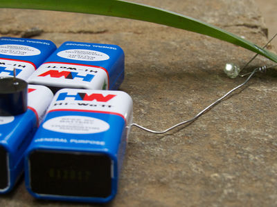
We made a switch which would basically light up a LED by making current flow through the four of us and enter the LED. It was quite an adventure as we connected ten 9v batteries together and each time we touched it we would get small shocks. We were later informed that the permitted limit is only 9v, after which we all had a good laugh. The other switch we made consisted of a thermistor which we used to light up another LED. We even tried calculating the conductivity of leaves and lighting up a LED. We enjoyed the process of exploring various sensors and also looking at everyone else's projects.
Resistors
Fixed Resistors
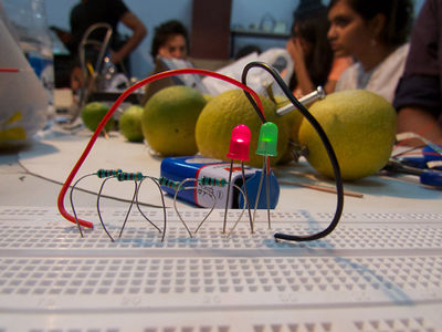
I vaguely recollect learning about connecting circuits in series and parallel though I was never shown it physically. Just in diagrams, which I think was pretty stupid. But now, I was actually able to grasp the concept quite easily and I was quite proud with myself.
Variable Resistors
Potentiometer
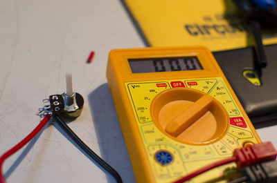
I was really surprised by the fact that I was able to understand what I was being taught. I remember being taught all of this in school but these were nothing but words and diagrams I never understood. Doing all of this in reality changed the way I understand things. The potentiometer seemed really interesting to me, especially when it was mentioned that it was basically the volume control of radios and other devices. I immediately thought of all the other things I could control with this, ranging from dimming the lights to a musical transposer or some sort of capo. (basically the pitch of a musical instrument)
Thermistor
The thermistor is one of the more interesting sensors. The more I got to know its functionality, the more I recognized all the devices using the thermistor. Smoke detectors, device warming warnings, etc. This was when I started getting a good hang of the connectivity and placing of the devices.
LDR
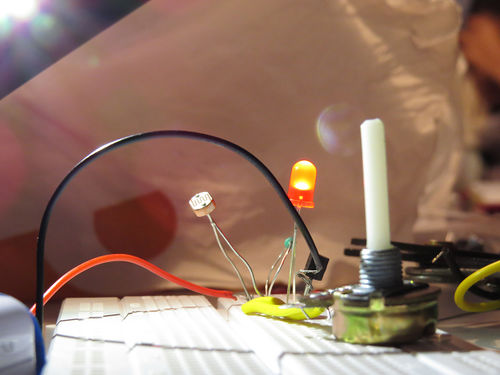
The LDR really fascinated me as I, just like in other sensors, was thinking of all the various possibilities of the sensor. The more I thought about it, I came to realize that it could act like a kind of light sensor if it was a bit tampered with, and that came true later on in the course when the Arduino was introduced.
Capacitors
I didn't quite understand the function of capacitors at first and was quite confused about its connections and why it was placed the way it was but then later I started applying my common sense to it and understood why the circuit was placed that way. From then on, I started using my mind also rather than just looking at diagrams and copying what was happening.
Diode
I understood the basic functionality of the diode and we just conducted an experiment which lit a LED, but I don't understand what other uses it has. The experiment of lighting up the LED would've been the same even without the diode so I didn't get its utility.
Transistors
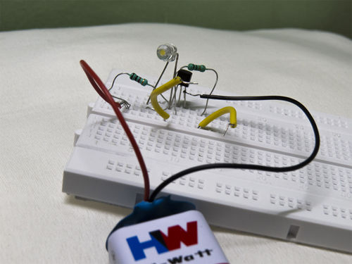
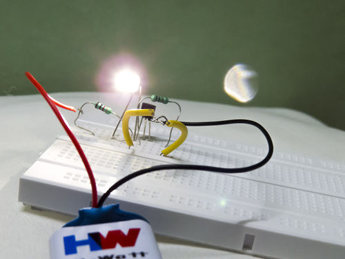
If I was not given the context of the transistor and how it affected the world, I would've thought of it like just another component. It's quite amazing how so much research had gone into coming up with that small part which can get lost before you know it. And the fact that every device we use utilize millions of them, it was quite overwhelming that I was being taught how to use them. This time we moved from two pins to three pins. At that time, I was still struggling a bit with the basic circuits and hence it was a little difficult for me to catch up with the connections. But eventually I could manage it and understand the concept as well.
555 oscillator
This was probably the toughest yet most fun experiment for me. It was tough in the sense that I couldn't figure out the circuit diagram at all initially. But after quite some time of struggling, I got it. I understood the realistic diagram that was drawn on the road better than the actual circuit diagram, which I still can't understand. The sounds just got more weird by the end of the class and none of us wanted to pay attention to what was being taught next. It was a great experience.
Here are the clips demonstrating the 555 oscillator.
Amplifier- LM386
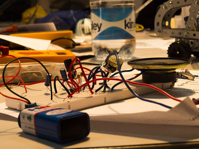
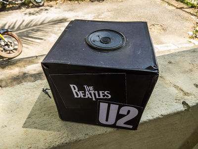
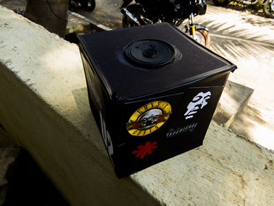
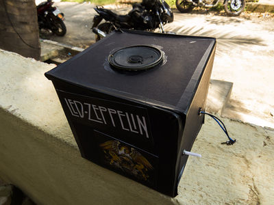
When we started working on the breadboard model of this in class, I knew it wasn't going to be easy. I still had some difficulty following the 8-pin circuit diagrams so I was already somewhat behind, but I was still quite excited about building my own amplifier. So it took me some time, but eventually Phil Collins and Bono were received quite well. The sound quality was good and none of the connections were loose. I was quite happy by the end of it. The soldering part at home was a pain, though. I kept trying and failing. I tried soldering it so many times but I couldn't get it to work. It was really frustrating. Until finally I realized that I had a few connections wrong and therefore rectified it all and finally got it working. The box was fun to make. It turned out quite neat by the end of it I think.
Arduino
Finally, the coding part. Earlier this year, I joined Code Academy and took up some tutorials on very basic HTML and CSS, which was basically to design the homepage of Airbnb. So that was all the HTML I knew. In the course description, when coding was mentioned, I didn’t think it would be about coding electrical components. So when we were asked to buy an Arduino, which I was told was something to code into, I thought it was a mini-computer of some sort. And when I got it, I saw that it was only a board. I was mildly disappointed. But when I did some research about the Arduino and all its possibilities, I was left in awe. There were so many projects that people had done and used it in so many creative ways, I was puzzled as to how I did not come to know of the Arduino before this course.
Blinking a LED
For the first assignment, when we were asked to blink a LED, I was quite excited. I already was getting the hang of the coding part. Since I was a little slower in class before, during the analog part of electronics, I thought I’d compensate by being a little ahead in the coding aspects at least. And that was finally happening. Blinking the LED was done quite easily and I was proud with myself. The commands were initially a little confusing but when they made sense to me, I found myself programming the commands I know with ease.
Knight Rider chasing lights
This was probably the coolest assignment. When we were shown the video at first, I thought it was a video played by mistake, because well, Knight Rider. But then as soon I saw the lights of the car, nostalgia struck and I was hoping that the assignment was what I was hoping it to be. And I was right. Yes. We were asked to figure the coding out. And before using common sense, I went onto the internet and checked various websites for solutions to it. Then, later on, I realized what an idiot I’d been for doing that, as the solution was right there. I just had to do the same thing again and again and send the command backwards as well. As simple as that. Once I’d done that, I got the lights to chase each other but I was still quite unhappy with the stupidity I’d done. At the end of the class, we were asked to come up with a magic trick! What.
This is the video where I have demonstrated the Knight Rider light chase.
LDR if and else video
LDR if and else with a capacitor video
Vibration motor video
Magic Box
It was impossible to come up with something that could qualify as a magic trick. This was the time I was doing heave research on the internet as to the possibilities of the Arduino in terms of a magic trick. While going through that, I found so many other projects that I would love to continue in the future when I had the time. I found a project which was basically a magic wand, which would glow LED’s in letter formats, and by using long exposure shutter speeds, one can display sentences through it. I also found a lot of uses for the ultrasonic sensor. And a few more other projects. But I was still unclear with my idea for the magic trick. My partner and I brainstormed and then after what seemed like a million hours, I came up with the idea of making a box that would make something disappear. The idea was quite simple. It was to make a box with three layers. In the lowest layer, there would be the Arduino and the soldered PCB circuit. The layer above that would just be covered in cloth and on the top-most layer, there would be the object I would want to make disappear. The other components included a LDR and 360 degree servo motor. So when I place a black cloth on top, I would bring my hand closer to the LDR, thus triggering the servo motor attached to the platform to spin and rotate the platform with it, thus making the ball fall on top of the cloth in the lower layer. And as the motor would do a complete 360 degree spin, I would move my hand away, thus making the object disappear. It would’ve turned out to be a neat trick, had the motor not failed. As I was attaching the motor to the platform, glue went inside it, thus jamming the rotation.
This is the video showing the spinning of the platform for the Magic Box:

