Difference between revisions of "Meera Sanghani"
| Line 6: | Line 6: | ||
'''Tilt Sensor'''<br> | '''Tilt Sensor'''<br> | ||
A Tilt Sensor or a Tilt Switch is a component that detects orientation of an object. There are different types of tilt sensors based on the axes it can measure. | A Tilt Sensor or a Tilt Switch is a component that detects orientation of an object. There are different types of tilt sensors based on the axes it can measure. | ||
| − | A simple tilt sensor is basically a switch that will turn ON or OFF based angle or orientation of the sensor. Such sensor is useful for single axis tilt detection.[[File:TiltSensor.JPG| 300px | + | A simple tilt sensor is basically a switch that will turn ON or OFF based angle or orientation of the sensor. Such sensor is useful for single axis tilt detection. |
| − | + | ||
| + | [[File:TiltSensor.JPG| 300px]]<br> | ||
| + | ===How does it work?=== | ||
The tilt sensor is cylindrical and contains a free conductive rolling ball inside with two conductive elements (poles) beneath. | The tilt sensor is cylindrical and contains a free conductive rolling ball inside with two conductive elements (poles) beneath. | ||
When the sensor is completely upright, the ball falls to the bottom of the sensor and connects the poles, allowing the current to flow. | When the sensor is completely upright, the ball falls to the bottom of the sensor and connects the poles, allowing the current to flow. | ||
When the sensor is tilted, the ball doesn’t touch the poles, the circuit is open, and the current doesn’t flow. | When the sensor is tilted, the ball doesn’t touch the poles, the circuit is open, and the current doesn’t flow. | ||
| − | This way, the tilt sensor acts like a switch that is turned on or off depending on its inclination. So, it will give digital information to the Arduino, either a HIGH or a LOW signal. <br>[[File:Tiltsensorwired.JPG| | + | This way, the tilt sensor acts like a switch that is turned on or off depending on its inclination. So, it will give digital information to the Arduino, either a HIGH or a LOW signal. <br>[[File:Tiltsensorwired.JPG| 300px]] |
| − | [[File:Tilt sensor.png| 300px | + | [[File:Tilt sensor.png| 300px|]] |
<br> | <br> | ||
<p> | <p> | ||
| Line 23: | Line 25: | ||
| − | Materials Used<br> | + | ===Materials Used=== |
| − | + | *Arduino,<br> | |
| − | Bread board, | + | *Bread board,<br> |
| − | Led/buzzer, | + | *Led/buzzer,<br> |
| − | Tilt sensor module, | + | *Tilt sensor module,<br> |
| − | Jumper wires | + | *Jumper wires<br> |
| + | |||
<br> | <br> | ||
| − | + | [[File:Materials.jpg|300px|]]<br> | |
| − | + | [[File:Circuit.png|300px|]]<br> | |
| − | + | [[File:Circuit diagram.png|300px|]]<br> | |
| − | + | ||
| − | + | ||
| − | + | ||
| − | + | ||
| − | [[File:Materials.jpg|300px | + | |
| − | [[File:Circuit.png|300px | + | |
| − | [[File:Circuit diagram.png|300px | + | |
| − | [[File:Code.png| 600px| | + | [[File:Code.png| 600px| ]] |
<br> | <br> | ||
| − | [[File:Tiltsensor.JPG| 600px| | + | [[File:Tiltsensor.JPG| 600px|]] |
== Turbidity Sensor == | == Turbidity Sensor == | ||
| + | Combining basic LDR circuit with an LED we created a turbidity detector .The essential factor to consider was casing the LDR in darkness. | ||
| + | |||
| + | [[File:Schematic.png|400px| ]] | ||
| + | ===Circuit=== | ||
| + | [[File:Led circuit.png| 400px| ]] | ||
| + | ===Arduino Code === | ||
| + | [[File:Code turbidity.png| 400px]] | ||
| + | ===Serial Reading=== | ||
| + | [[File:Serial moniter.png| 400px]] | ||
| + | ===Construction of the meter=== | ||
| + | [[File:Meera turbidity1.JPG| 400px]] | ||
| + | |||
| + | [[File:Meeraturbidity1.2.JPG| 400px]] | ||
| + | |||
| + | [[File:MeeraTurbidity2.JPG| 400px]] | ||
| + | |||
| + | [[File:MeeraTurbidity4.JPG| 400px]] | ||
Revision as of 23:48, 9 March 2017
Challenge Accepted
Task:Use motors
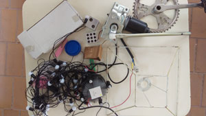
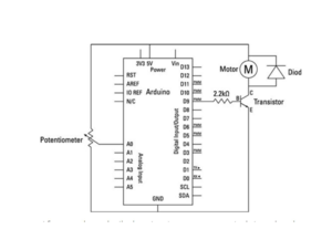
In the previous course the only encounter with motors was using them with a module and arduino. Transistors and diode circuits I hadn't touched upon. I had experimented with Unity and serial communication. I thought of creating something dance oriented but since we weren't having accelerometers but we're using motors there was a change of plans. The LDR circuit couldn't be easily stitched with the diode circuit just like two libraries being fused in the IDE. So we moved ahead with the potentiometer and remade the circuit in a compact format. As a consumer product I feel it can be a valuable addition to an artist's toolset. I expect to figure out the coding back end more smoothly through this course while keeping the sensor interaction simple.
Contents
Sensors
Tilt Sensor
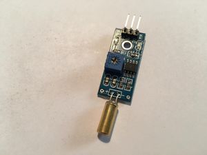
A Tilt Sensor or a Tilt Switch is a component that detects orientation of an object. There are different types of tilt sensors based on the axes it can measure.
A simple tilt sensor is basically a switch that will turn ON or OFF based angle or orientation of the sensor. Such sensor is useful for single axis tilt detection.
How does it work?
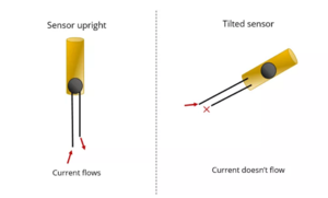
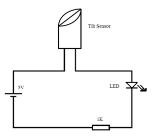
The tilt sensor is cylindrical and contains a free conductive rolling ball inside with two conductive elements (poles) beneath.
When the sensor is completely upright, the ball falls to the bottom of the sensor and connects the poles, allowing the current to flow.
When the sensor is tilted, the ball doesn’t touch the poles, the circuit is open, and the current doesn’t flow.
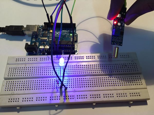
This way, the tilt sensor acts like a switch that is turned on or off depending on its inclination. So, it will give digital information to the Arduino, either a HIGH or a LOW signal. 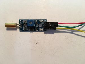
Materials Used
- Arduino,
- Bread board,
- Led/buzzer,
- Tilt sensor module,
- Jumper wires
Turbidity Sensor
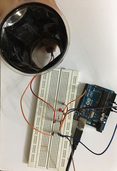
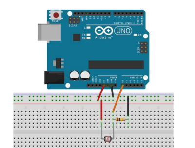
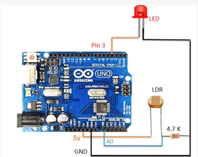
Combining basic LDR circuit with an LED we created a turbidity detector .The essential factor to consider was casing the LDR in darkness.
Circuit
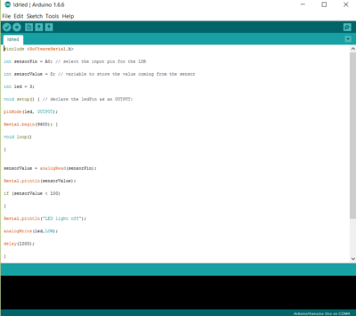
Arduino Code
Serial Reading
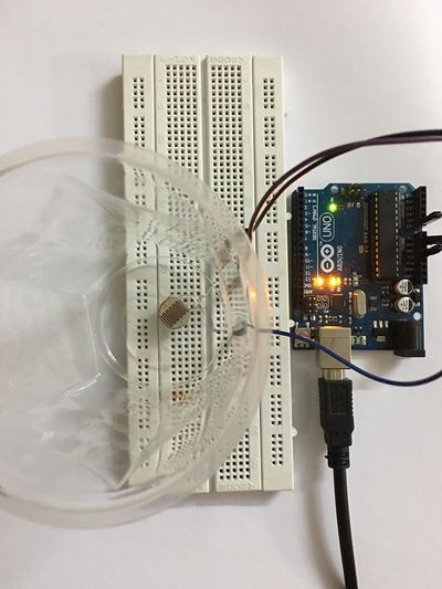
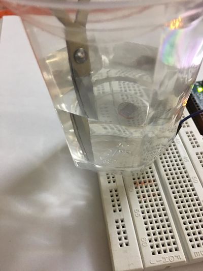
Construction of the meter
